phatcreators
Full Member level 5
what's the advantage of using 4 core cable over 3.5 core cable ? And then, what changes do we have to make for the neutral size & earth size cable calculation ?
thanks
thanks
Follow along with the video below to see how to install our site as a web app on your home screen.
Note: This feature may not be available in some browsers.
Some general info (thumb rules)...
Neutral conductor must be at least 1/2 the size of other conductor.
It is theoraticaly explained , that algebric sum of all the phases when in balanced condition
then neutral current will be zero.
Now suppose one phase fail i.e. total unbalanced condition its neutral conductor will provide
a return path and its current will be half the load on other phases so by this
result on neutral conductor for every unbalanced condition its current will not exceed
the rated value (same as in phase conductors).
The selection of neutral conductor depends on the nature of loads, such as the load harmonics
(more than 20% loads are electronic) or the load balancing (most of the loads are 3 phase motor) etc, etc.
So, there are few general cases to consider here:
1. If the loads are almost balanced and there is no significant electronic loads, you can select 3.5 (3 + 0.5)
2. If the loads are not balanced and there is no significant electronic loads, you can select 4 (3 + 1)
3. If the loads are balanced and there is significant electronic loads, you can also select 4 (3 + 1)
4. If the loads are not balanced and there is significant electronic loads, you need to select even higher size
for neutral (3 + 1.5)
With modern equipment it is getting to be a major problem especially with IT gear.
Some cable manufacturers can now supply cable with a neutral 1.5 X phase conductor.
How to check & measure whether the load is balanced without any cabling ?
What are the examples of significant electronic loads ?
Measuring without cables ??? Impossible.
We can say that 3-phase load is balanced, when load impedance in each phase has same value.
( This means that resistance and reactance in every phase has same value , i.e. currents and cos(phi)´s are equal too.)
This means all the loads that generate harmonic distortion in the power grid.
for ex. electronic power supplies, motor inverters, thyristor- and triac power controllers, electronic lamp ballasts, etc,etc....
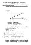
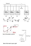
Here is one way to find some approximate values.....
This is useful only for light loads (current = few amperes )
View attachment 67277
what do you mean by warning that you gave in the attachment ?
without harmonics
Presume, pure real power input without imaginary (reactive) part