Continue to Site

Welcome to EDAboard.com

Welcome to our site! EDAboard.com is an international Electronics Discussion Forum focused on EDA software, circuits, schematics, books, theory, papers, asic, pld, 8051, DSP, Network, RF, Analog Design, PCB, Service Manuals... and a whole lot more! To participate you need to register. Registration is free. Click here to register now.

What to do with grounds on either side of a power transformer?

Status
Not open for further replies.

KX36

Junior Member level 2
Joined
Jul 16, 2011
Messages
23
Helped
2
Reputation
4
Reaction score
2
Trophy points
1,283
Visit site
Activity points
1,579
Hi all,

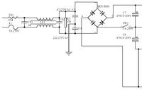
I've been reading up on switched mode power supplies just as general interest, and this is the first time I've looked at a circuit with any significant electronics on the primary side of the transformer, connected to mains. I have seen in many circuit block diagrams that the ground connections on either side of the transformer have different symbols. Here's an example circuit diagram I quickly found to show what I'm talking about incase it's not clear, note the ground symbols on either side of the transformer.
Fan6300-Highly-Integrated-Quasi-resonant-Pwm-Controller.jpg


I would assume this means the grounds can't be connected together in order to maintain the galvanic isolation of the secondary side from the mains for safety; so what do you normally do with these two grounds when they both need to be grounded but can't be connected?

My guess would be that it involves a capacitor, like in the olden days when some countries used 2-prong power cords without a protective earth connection and "ground" was just a series capacitor from neutral. If it is a capacitor connecting the two grounds, is this one of those situations where it legally has to be a class X/Y capacitor etc, and which side would be connected to the protective earth?

Cheers,
Matt
 

Re: What do do with grounds on either side of a power transformer?

For the pure switched mode converter operation, there's no need to connect the secondary ground anyhow. The secondary can be just floating. Presuming correct clearance, particularly in the transformer design, it can act as class 2 (safe isolation based) power supply.

There's however a problem of high frequency emissions of the switching frequency and it's harmonics. To "drain" the interference currents injected e.g. in the transformer, an Y-capacitor between primary and secondary ground can be a solution. Some switched mode power supplies also have a PE connection of the secondary ground. Then Y-capacitors are between primary ground respectively mains live and neutral and PE.
 
Re: What do do with grounds on either side of a power transformer?

Some switched mode power supplies also have a PE connection of the secondary ground. Then Y-capacitors are between primary ground respectively mains live and neutral and PE.

I'm not sure that I understand this last sentence entirely, about what capacitors have to connect to. Could you please clarify the connection of each capacitor and the connection of PE when the secondary has to be grounded for whatever reason?

Thanks,
Matt
 

Re: What do do with grounds on either side of a power transformer?

Y capacitors are used for EMI reduction, and there placement depends on the EMI suppression concept implemented in the design, e.g. if filter chokes are used. There are different options. See the X and Y capacitors from a standard ATX (PC desktop) power supply as an example. The ATX standard generally requires a 3-wire power cable and has the secondary ground tied to PE.

 
Re: What do do with grounds on either side of a power transformer?

Sorry for my newbiness, but I'm still struggling to understand how both primary and secondary can be safely grounded to pass safety tests while keeping their two grounds isolated. So, please correct me here:

X capacitors connect Live to Neutral, often for the purpose of input filtering EMI together with the common mode choke.
Y capacitors connect Live to PE, or Neutral to PE, also for the purpose of input filtering EMI.
There is also an optional Y capacitor between primary and secondary grounds to reduce EMI from switching noise
The secondary side ground can be connected to PE (and this is the case that I'm interested in).
And the primary side ground connects to... something... not directly to PE if the secondary ground is (?) as that would null the galvanic isolation between primary and secondary... but it does still have to be able to pass fault currents to PE to pass safety tests (?)...

So what am I missing?
 

Re: What do do with grounds on either side of a power transformer?

Grounding of the secondary basically doesn't change anything to requirement of double respectively reinforced insulation between primary (mains) and secondary (SELV) side. If Y capacitors are connected across the insulation barrier, they have to be qualified sufficiently.

The primary ground of a bridge rectifier supplied primary side is a floating potential, carrying superimposed AC and DC voltages. As I previously mentioned, you often see Y capacitors between primary and secondary grounds for small SMPS without PE connections, because they most effectively drain the high frequent currents injected between the transformer windings. They are unusual for SMPS with PE connection like the shown ATX supply.
 
Re: What do do with grounds on either side of a power transformer?

The primary ground of a bridge rectifier supplied primary side is a floating potential, carrying superimposed AC and DC voltages. As I previously mentioned, you often see Y capacitors between primary and secondary grounds for small SMPS without PE connections, because they most effectively drain the high frequent currents injected between the transformer windings. They are unusual for SMPS with PE connection like the shown ATX supply.

I think this bold line is probably my answer, that the primary ground is floating. What implications does this have for the tests that equipment has to go through before being sold then? From what I've read, the discharge path of ESD and fault currents on the primary is a significant design point for these things. Would it just discharge through the bridge rectifier back into the neutral wire of the mains?
 

Re: What do do with grounds on either side of a power transformer?

For the pure switched mode converter operation, there's no need to connect the secondary ground anyhow. The secondary can be just floating. Presuming correct clearance, particularly in the transformer design, it can act as class 2 (safe isolation based) power supply.

There's however a problem of high frequency emissions of the switching frequency and it's harmonics. To "drain" the interference currents injected e.g. in the transformer, an Y-capacitor between primary and secondary ground can be a solution. Some switched mode power supplies also have a PE connection of the secondary ground. Then Y-capacitors are between primary ground respectively mains live and neutral and PE.


Dear FvM,

You replied that:

For the pure switched mode converter operation, there's no need to connect the secondary ground anyhow. The secondary can be just floating. Presuming correct clearance, particularly in the transformer design, it can act as class 2 (safe isolation based) power supply.

Could you please tell me the reason that why secondary can be floated in isolated SMPS? I am asking you because I am designing a isolated full-bridge boost converter and wondering whether I should ground the secondary side circuit (full wave rectifier) or not. Some one told me it depends on your application but I am not sure what does it mean.

Please guide me whether secondary side needs to be connected to ground or not? and if Yes, then in which applications?

Your reply will be really appreciated.

Thank you.
 

Re: What do do with grounds on either side of a power transformer?

There is a large common mode noise generated with floating SMPS that can be problematic for unbalanced sensitive circuits. e.g. external microphone inputs on laptops. Although primary side grounding reduces conducted noise getting back into the line, there is always a coupling capacitance from primary to secondary coil. When no secondary ground is used to absorb this stray electric field it results in a differential input noise. In this case, secondary grounding is a useful step for AC line noise reduction.

On the other hand, the leakage or coupling capacitance across the SMPS transformer at switching slew rates can also result in secondary ground current on the case when in contact with skin and exceed the 500uA safety limit. One can verify this by RF measurement or using the metal edge of a laptop against the kneecap , which is very sensitive to low currents at high current density and may feel like a burn. I have noticed this effect on iPad's and ACER laptops outdoors in the patio with an extension cord on the laptop charger in moist grass. ( Both have primary grounding only) .

These are not UL safety tests but rather two real-world examples where secondary grounding might be useful assuming there are no other faulty equipments on the same circuit with a ground fault.
 
Re: What do do with grounds on either side of a power transformer?

SunnySkyguy,

Thanks a lot for the reply. But could you please name me some industrial applications where the grounding of secondary side of isolated SMPS needs to be grounded and some applications where grounding of secondary side is not required.
 

Re: What do do with grounds on either side of a power transformer?

Dear FvM,

You replied that:

For the pure switched mode converter operation, there's no need to connect the secondary ground anyhow. The secondary can be just floating. Presuming correct clearance, particularly in the transformer design, it can act as class 2 (safe isolation based) power supply.

Could you please tell me the reason that why secondary can be floated in isolated SMPS? I am asking you because I am designing a isolated full-bridge boost converter and wondering whether I should ground the secondary side circuit (full wave rectifier) or not. Some one told me it depends on your application but I am not sure what does it mean.

Please guide me whether secondary side needs to be connected to ground or not? and if Yes, then in which applications?

Your reply will be really appreciated.

Thank you.

Dear FvM,

Awaiting for your reply.
 

Dear FvM,

Awaiting for your reply.
I believe that others can well or possibly better answer the question.

For usual off-line switched mode SMPS, I agree with SunnySkyguy that secondary grounding should be prefered if it can be easily achieved. It offers a safety extra in case of an internal insulation fault.

But you are apparently talking about a boost converter. In this case, the "extra safety argument" may be reversed, isolation of the secondary is like a safety transformer. Application requirements or specific safety regulations might impose earthing though.

Dear FvM,

Does it mean that if I do not ground the secondary side of isolated boost converter, it is Ok to do so? Does it mean that it is SMPS designers choice to decide on grounding or not grounding the secondary side?

Thank you.
 

Status
Not open for further replies.

Part and Inventory Search

Welcome to EDABoard.com

Sponsor

Back
Top