Continue to Site

Welcome to EDAboard.com

Welcome to our site! EDAboard.com is an international Electronics Discussion Forum focused on EDA software, circuits, schematics, books, theory, papers, asic, pld, 8051, DSP, Network, RF, Analog Design, PCB, Service Manuals... and a whole lot more! To participate you need to register. Registration is free. Click here to register now.

What to connect in the input 2 of the given diagram

Status
Not open for further replies.

rajaram04

Advanced Member level 3
Joined
Jun 17, 2012
Messages
871
Helped
6
Reputation
12
Reaction score
5
Trophy points
1,298
Location
earth
Activity points
7,687
Hello sir
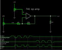
here in the given diagram of 741 op amp i.c. a schmitt trigger is shown but having two inputs so what to connect & where in the inputs ?


schmitt-trigger-circuit-using-741.jpg
 

I don't think you want to connect anything to input 1, that looks like your reference voltage (which is set by the pot, R2). Connect your signal to input 2.
 

If you send the signal to the non-inverting input, then the signal must come through some amount of resistance, in order for the hysteresis to work reliably.

Or if you wish you can send the signal to the inverting input. It depends on whether you want the output to be inverted or not.


Since your op amp is labelled 741, remember that the 741 output does not go below 2V, when powered from a single supply.


okk sir thanks , You have shown here tw0 presets in the diagram but values are not mentioned , please tell
 

okk sir thanks , You have shown here tw0 presets in the diagram but values are not mentioned , please tell

The potentiometers are an easy way to select any volt level you wish. Their value is not critical. The default is 1000 ohms.

Falstad's simulator allows you to move a slider, to change its value, while the simulation is running. Just as if it were a real potentiometer. The scope traces tell the story.

The pots can stand in for (a) whatever is your signal level going to one input, and (b) whatever voltage reference you choose going to the other input.
 

hmm kk sir , actually i designed simple op amp configuration as a pre stage & input is connectrd to photo diode in a simple way & next stage i made is the circuit i am showing above , output from first stage is fed to the next one but in that case the schmitt trigger is not working as per rule , the output changes accordance to the the input of I.R. rays on the photo diode
 

the output changes accordance to the the input of I.R. rays on the photo diode

Then it sounds as though the op amp is in comparator mode.
Assuming you need a schmitt trigger, then you want hysteresis action.
The hysteresis is very tricky to get adjusted properly.
Try different values for the feedback resistor. The lower its resistance, the wider the hysteresis envelope.
Each time you change the feedback resistor you will probably need to re-adjust the reference V too.

Since your circuit has several stages, you must make sure each stage produces an output that is in a usable voltage range, for the next stage.
 

kkk sir you mean to say the resistor at pin 3 (100k) in series wih 68k from the output ?
 

kkk sir you mean to say the resistor at pin 3 (100k) in series wih 68k from the output ?

The 100k is a positive feedback resistor. You can change its value to whatever you wish, in order to obtain whatever range of hysteresis you need.

It can be 68k, if you wish. Or is it a different 68k resistor that you are talking about?

- - - Updated - - -

Now I see, there is a 68k in your original schematic.

When I created my simulation, I added that resistor network at the output. It did not seem to affect anything. Therefore I removed it. My simulation still performed as a schmitt trigger. So I posted the schematic in post #3. That is a building block. It is up to you to adapt it to your purposes.
 

Status
Not open for further replies.

Part and Inventory Search

Welcome to EDABoard.com

Sponsor

Back
Top