Continue to Site

Welcome to EDAboard.com

Welcome to our site! EDAboard.com is an international Electronics Discussion Forum focused on EDA software, circuits, schematics, books, theory, papers, asic, pld, 8051, DSP, Network, RF, Analog Design, PCB, Service Manuals... and a whole lot more! To participate you need to register. Registration is free. Click here to register now.

what is the amperage of a 300 KW load ? thanks

Status
Not open for further replies.

munzir

Full Member level 6
Full Member level 6
Joined
Oct 11, 2011
Messages
365
Helped
22
Reputation
44
Reaction score
21
Trophy points
1,298
Location
Pak
Activity points
3,795
what is the amperage of a 300 KW load ? How to calculate it ?

what size of the cable should be selected for 300 KW load ?

The load is resistive + inductive

what would be the voltage drop in the cable (suggested for the 300 KW load) ? And, at what size or for what size we calculate the voltage drop means after what length we consider the voltage drop in the cables or conductors ?

Should the selected cable be a single 4 core cable (including 3 phases + neutral or earth) OR should there be individual cables (including 3 cables of same size for 3 different phases & 2 cables of same size for neutral & for earthing) ? Which would be better to select ?

Should the selected cable is made of copper ? not of silver or aluminium ?

thanks
 

what is the voltage of the system and need more info on the load is it a motor? if so need to know horse power,
 
  • Like
Reactions: munzir

    munzir

    Points: 2
    Helpful Answer Positive Rating
3 phase 440 V ..... the length of the cable (conductor) from DB to the machine is about 50 metres

yes ..... heaters + 3 phase AC induction motors
 

Ballpark figures (based on a table of wire gauges and Ohm's law)(copper wire assumed):

300 KW, divided by 440 V, equals 681 amps.

Split among 3 cables, gives 227 amps per cable.

50 meter distance makes 100 meter round trip. This is about 330 feet. Total length 985 feet (call it 1000).

A wire table states 00 (double-ought) gauge as the smallest safe gauge to carry that much current. Diameter 365/1000 of an inch. Resistance is .0779 ohm per thousand feet.

At 1000 feet the total voltage drop will be 17.7 volts.
Times 227 amps makes power losses 4014 watts.

This assumes you'll need all three return wires. It may or may not be possible for a metal-to-soil contact (or three of them) to be made conductive enough and reliable enough to carry 227 amps.

==================

What if you upgrade to 000 (triple-ought, diameter 409/1000 of an inch)?

Resistance for 1000 feet is .0618 ohm.

Voltage drops will total 14.03 V.
Times 227 amps makes power losses total 3184 watts.

===========

Whether you should choose the thicker wire will most likely depend on which costs more: (a) the wire, or (b) the cost of generating additional power to make up for losses in the thinner wire as opposed to the thicker wire.
 
what is the amperage of a 300 KW load ? How to calculate it ?

In 1-Phase systems
P = U*I*cos(Phi)

In symmetrical 3-Phase systems ( = equal phase loads )
P = sqrt(3)*U*I*cos(Phi)

Three Phase Calculator

what size of the cable should be selected for 300 KW load ?

It´s not so simple with industrial installations in this size.
You must know and understand all the national recommendations and regulations.
Usually bigger installations and wirings must have legally authorized person responsible for
all the work done in project.
read this for example.........
General method for cable sizing - Electrical Installation Guide

Cable Sizing Tool

**broken link removed**

Should the selected cable be a single 4 core cable (including 3 phases + neutral or earth) OR should there be individual cables (including 3 cables of same size for 3 different phases & 2 cables of same size for neutral & for earthing) ? Which would be better to select ?

You should check the manufacturer`s recommendations.
 
Last edited:
In 1-Phase systems
P = U*I*cos(Phi)

In symmetrical 3-Phase systems ( = equal phase loads )
P = sqrt(3)*U*I*cos(Phi)

Three Phase Calculator


It´s not so simple with industrial installations in this size.
You must know and understand all the national recommendations and regulations.
Usually bigger installations and wirings must have legally authorized person responsible for
all the work done in project.
read this for example.........
General method for cable sizing - Electrical Installation Guide

Cable Sizing Tool

**broken link removed**


You should check the manufacturer`s recommendations.

why the power factor is taken 0.95 here in this calculator ? Three Phase Calculator

What value of power factor should be taken into account ? (As i know three phase voltage is 400 V , three phase power 300 KW, single phase voltage is 230 V) and then what is the amperage in a 3 phase system ? Should i use this formula : P = sqrt(3)*U*I*cos(Phi) ?

thanks
 
Electrical loads consuming alternating current power consume both real power and reactive power. The vector sum of real and reactive power is the apparent power. The presence of reactive power causes the real power to be less than the apparent power, and so, the electric load has a power factor of less than 1.

Cables include reactive elements too.

The reactive elements can create voltage fluctuations and harmonic noise when switched on or off. They will supply or sink reactive power regardless of whether there is a corresponding load operating nearby, increasing the system's no-load losses. In the worst case, reactive elements can interact with the system and with each other to create resonant conditions, resulting in system instability and severe overvoltage fluctuations. As such, reactive elements cannot simply be applied without engineering analysis.

The distortion power factor describes how the harmonic distortion of a load current decreases the average power transferred to the load.

Distortion power factor = 1 / (SQRT ( 1 + THDi^2)) = I1rms / Irms

THDi is the total harmonic distortion of the load current. This definition assumes that the voltage stays undistorted (sinusoidal, without harmonics). This simplification is often a good approximation in practice. I1,rms is the fundamental component of the current and Irms is the total current - both are root mean square-values.

The result when multiplied with the displacement power factor (DPF) is the overall, true power factor or just power factor (PF):

PF = DPF * I1rms / Irms

More info
Power factor - Wikipedia, the free encyclopedia

Should i use this formula : P = sqrt(3)*U*I*cos(Phi) ?
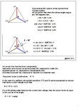
About above formula.............

3PhasePower&Vectors_01.jpg
3PhasePower&Vectors_02.jpg
 
you should use 300mm2 , 3.5 core cable of copper .......... or you may use 3 separate cables of single core of about 95mm2 for the three phases & 2 separate 16mm2 cables one for neutral & one for earth .........

hope it helped
 
  • Like
Reactions: munzir

    munzir

    Points: 2
    Helpful Answer Positive Rating
would anybody explain this to me , how dinesh has calculated the wire size ? (including dinesh & KAK)

thanks
 
Hope this explain something...................

P = SQRT(3) * U * I * cos(Phi)
I = P / (SQRT(3) * U * cos(Phi)) >> ( power factor ) PF = cos(Phi)

300kW >> 400V >> PF=1 >> 433A/phase
300kW >> 400V >> PF=0.90 >> 481A/phase
300kW >> 400V >> PF=0.80 >> 541A/phase

Next .........look cable manufacturer´s databook or manual and check

Current -carrying capacities for different installation methods
for ex. **broken link removed**

check for PF=1 >> 433 A
-multi-core cable , three loaded conductors , method E >>> 430Amp´s >>> 240mm²
-single -core cable , three loaded conductors Trefoil, method F >>> 485Amp´s >>> 240mm²
-single -core cable , three loaded conductors Flat, (=Cable Tray), spaced horizontal method G >>> 456Amp´s >>> 150mm²
-single -core cable , three loaded conductors Flat, (=Cable Tray), spaced vertical method G >>> 480Amp´s >>> 185mm²

Now you know ,
-if single 3-phase cable is used 3 x 240mm² conductors are needed
-if 3 x single core cabel is used 3 x 240mm² cables are needed , when binded tight together (Trefoil)
-if 3 x single core cabel is used 3 x 150mm² cables are needed , when assembled horizontal and spaced in cable tray or free air
-if 3 x single core cabel is used 3 x 185mm² cables are needed , when assembled vertical and spaced in cable tray or free air

Note that used table is for PVC / Copper Cable and when ambient temperare is 30 C and conductor temp. remains < 70 C

**broken link removed**

Next check EPR/XLPE Cable Current Ratings (Copper) for PF=1 >> 433A
and you find that for this cable type ................
--multi-core cable , three loaded conductors , method E >>> 456Amp´s >>> 185mm²
-if single 3-phase cable is used 3 x 185mm² conductors are needed
-single -core cable , three loaded conductors Flat, (=Cable Tray), spaced horizontal method G >>> 430Amp´s >>> 95mm²
-if 3 x single core cabel is used 3 x 95mm² cables are needed , when assembled horizontal and spaced in cable tray or free air

Note that these values are calculated and selected when PF=1 and ambient temperature <30 C and with optimum grouping factor.
It is very important to check these factors,because they can double cable conductor size.

Next check Derating factors for ambient air temperatures other than 30 C.
**broken link removed**

If many cables are bundled together check Grouping Derating Factors
**broken link removed**

If Cable Impedance calculations is needed, general values found here.................
**broken link removed**

at last check voltage drop and power loss in selected cable.

All above tables and more info................
**broken link removed**

Software Tools , basic calculations to IET compliant cable sizing. Feel free to browse and try
Tools

Good information about cables and lots of needed tables...............
**broken link removed**

About neutral conductor............
-some supply systems do not use any neutral conductor, this usually in cases when device supply is
connected right to the supply transformer without star-point.
-device manufacturer gives instructions for sizing of neutral conductor.
-the most safe way is to use the same size for neutral and phase conductors.

About earth wire...............
IEEE Wiring Regulation has stated....
for circuit using 16mm sq and below, earth shall be follow the live conductor size...
while 16mm to 35mm sq, the earth cable shall be 16mm,
anything above 35mm sq, the earth cable shall be at least 1/2 the size of the live conductor...
 
Last edited:
very well explained ....... thanks for your great effort ......

would you tell me , what's the benefit (advantage) of using 3 single core different cables of 95 mm2 rather than a single 3.5 core cable of 300 mm2 ?

Also because if the AC clamp meter measures 140 A per phase (starting load including spikes) then what would be the total amps (load) of the device ? Should we sum all the three values i.e. 140 + 140 + 140 = 420 Amps or should we use the same formula : P = V * I * sqrt 3 * cos phi and then calculate the total amps ?
 

would you tell me , what's the benefit (advantage) of using 3 single core different cables of 95 mm2 rather than a single 3.5 core cable of 300 mm2 ?

You should check the needed cable prices

My example calculations in post #10 ..............
Next check EPR/XLPE Cable Current Ratings (Copper) for PF=1 >> 433A
--multi-core cable , three loaded conductors , method E >>> 456Amp´s >>> 185mm²
-if single 3-phase cable is used 3 x 185mm² conductors are needed + Neutral conductor xxx mm² + Earth wire 95mm² minimum
-single -core cable , three loaded conductors Flat, (=Cable Tray), spaced horizontal method G >>> 430Amp´s >>> 95mm²
-if 3 x single core cabel is used 3 x 95mm² cables are needed , + Neutral conductor xxx mm² + Earth wire 50mm² minimum
when assembled horizontal and spaced in cable tray or free air

Note that these values are calculated and selected when PF=1 and ambient temperature <30 C and with optimum grouping factor.
It is very important to check these factors,because they can double cable conductor size.


About 3.5 core cable ( ie. neutral conductor = 0.5 times phase conductor )

Generally using of 3.5 core supply cable depends on load,

If cable is used for inductive load e.g.motor, in case if there is any fault then 1/2 core is sufficient to carry fault current due to lagging power factor.

in example case 3.5 core cable should be Phases 3x185mm² + Neutral 95mm² + Earth 95mm²

However, in resistive load we are using 4 core cable since there is power factor = 1.

in example case 4 core cable should be Phases 3x185mm² + Neutral 185mm² + Earth 95mm²

About 3 single core different cables

in example case 3 x single core cable should be Phases 3x 95mm² + 1x Neutral 95mm² + Earth 50mm²
must be installed and secured exactly according to the instructions in method G


Method G - Single-core cables laid flat and spaced in free-air
This method applies to cables installed on cable ladder, perforated cable tray or cleats provided that the cable is spaced more than 0.3 x D (overall diameter of the cable) from the wall and with at least 1 x D spacings between cables. Note that cables installed on unperforated cable trays are classified under Method C. This method also applies to cables installed in air supported by insulators.
The cable or insulated wire shall be installed such that the dissipation of heat is not impeded, whereby
allowance shall be made for heating by other sources and for irradiation by sunshine. Natural convection
shall not be obstructed.

Generally in all cases cable armoring can be used as earth conductor , check that conductor cross-sectional area is sufficient .

AC clamp meter measures 140 A per phase (starting load including spikes) then what would be the total amps (load) of the device ?

P = SQRT(3)*U*I*cos(Phi)
if cos(Phi) = 1 then P = 1.7321*400*140A*1 >> 97 kVA

if each phase input current is 140A , input power to device is 97kVA when supply voltage is 400V (between phases)

If this is maximum power of the device cables should calculate cables for 100kW power or simple find cable for 140A / phase by looking
cable sizing tables.
Remember to use some safety factor for high temperatures and over-currents. ( I would use factor as 1.2...1.25)

Where did you get 300kW , now we are talking power of 100kW......?????
 
for 133 Amps of current , power factor 0.8 , voltage 3 phase AC 400 V ....... for 100 feets

what size cable should be used ?

what would be the output power in KW ?

What should be the capacity of the breakers used outside the panel ?

what size of lugs should be used with the cable ?

Connected load should be considered in calculating cable size of the machine or the running load ?

thanks
 
  • Like
Reactions: munzir

    munzir

    Points: 2
    Helpful Answer Positive Rating
kindly, provide me the wiring gauges & their respective current handling capabilities at a particular temperature ........ for about 3-phase system 400 V & also for the single phase system 230 V .........

when we say that the cable has the size of 160mm2 then does this mean that the area of the whole cable (including outer or main insulation) is included i.e. the outer sheath ? or has the area of 160mm2 for each phase wire or cables present inside the cable (including the PVC insulation of each 3 phase wires or cables) ?

thanks
 
Last edited:

what would be the output power in KW ?

[ 3-Phase , 400V , 133A , PF=0.8 ]
Cos(Phi) = PF = 0.8 >> Phi = 37 degr.


Input Three Phase Total Power (kVA) 92.15kVA
Input Three Phase Real Power (kW) 73.72kW
Calculated Reactive Power (kVAr) 55.29kVAr

Cable current 3 x 133A

what size cable should be used ?

Table 4D1A - Single core 70ºC thermoplastic insulated page 206
Table 4D2A - Multicore 70°C thermoplastic insulated page 214

Current-carrying capacity (Amperes):
70ºC thermoplastic
insulated cables, nonarmoured,
with or without sheath (copper conductors)
Ambient temperature: 30°C
Conductor operating temperature: 70°C

Reference Method A
(enclosed in conduit in thermally insulating wall etc.) single core 70mm² multicore 95mm²

Reference Method B
(enclosed in conduit on a wall or in trunking etc) single core 50mm² multicore 70mm²

Reference Method C
(clipped direct) single core 50mm² multicore 50mm²

Reference Method F
3 cables, threephase A.C trefoil, single core 35mm² multicore 35mm²

Table 4B1 - rating factors for ambient air temperatures
other than 30ºc to be applied to the currentcarrying
capacities for cables in free air
Page 184

Insulation >> 70ºC Thermoplastic

Ambient
temperature ºC .....Factor
25............................1.03
30............................1.00
35............................0.94
40............................0.87
45............................0.79
50............................0.71
55............................0.61
60............................0.50
65 -
70 -
75 -a For higher ambient temperatures, consult manufacturer.


General Electrical Data

Conductor Resistance
Current Ratings
Installation Data

pages 161.........>>>>

**broken link removed**


I recommend to select one size bigger are than calculated here
ie. 35mm² >> 50mm² , 50 >> 70 , 70 >> 95 , 95 >> 120 etc.....

Neutral conductor same size as phase conductor.
Earth conductor , minimum 0.5* phase conductor.

What should be the capacity of the breakers used outside the panel ?

Here is one site , where you can select circuit breakers...........

**broken link removed**

-look product selector and documents & downloads

for ex.
Schneider Electric
JDA36150 Circuit Breaker
Molded Case Circuit Breaker (J-Frame) 150A, 3-Pole, 600 Vac, ABC, I-Line Plug-On
or equivalent type......

when we say that the cable has the size of 160mm2 then does this mean that the area of the whole cable (including outer or main insulation) is included i.e. the outer sheath ? or has the area of 160mm2 for each phase wire or cables present inside the cable (including the PVC insulation of each 3 phase wires or cables) ?

Usually when talking about 3-phase cable size , we are meaning size of one phase conductor.
Much more informative way is tell the cable structure .
for ex. 3x120mm² + 70mm² or 4x70mm² + 35mm² ( power conductors + earth ( armor ))
 
Last edited:
what is the wire size required voltage drop in 230 Volt circuits (single phase) & for 3-phase system (400 V) ?

when do we prefer to use stranded (flexible) wire & when the PVC sheathed wire ?

when do we prefer to use stranded (flexible) cable & when the PVC sheathed cable ?

thanx
 

what is the wire size required voltage drop in 230 Volt circuits (single phase) & for 3-phase system (400 V) ?

Usually we can use 5% voltage drop as max. value for cabling 230V or 400V,
but remember you must take into account all the components from supply point to the consumer point.

You can calculate yourself
here is table................
CSE Cables  Voltage Drop Calculations Table2.jpg

here is example...............

for ex. what is voltage drop in 3-phase cable 50m , when current is 125A and cable conductor is 70mm²

so.... look table copper trefoil 70mm² >> 0.534 mV/A/m

whole lenght is 2*50= 100m

Volt drop = 0.534 * 125 * 100 mV = 6675mV = 6.68V

6.68*100/400 = 1.67%

400V >> 5% is 20V what is current?

I = 20 * 1000 / ( 0.534 * 100 ) A = 374.5A
 
Kak , you didn't provide the wire size chart for 3-phase system (400 V) ?

Also, why did you double the length, whole lenght is 2*50= 100m ??

thanks a lot
 

you didn't provide the wire size chart for 3-phase system (400 V) ?

Read your post carefully.............. in my post #15

**broken link removed**

General Electrical Data
Current Ratings and Volt Drops

page 164 Cable Installation Reference Methods
page 180 Procedure for calculating continuous current rating
page 182 Table 4A3 Schedule of cable specifications and current rating cables
page 184 Table 4B1 Rating factors for ambient air temperatures other than 30°C
page 186 Table 4B2 Rating factors for ambient ground temperatures other than 20'C
page 188 Table 4B3 Rating factors for cables buried direct in the ground
page 190 Table 4C1 Rating factors for cable groupings
page 192 Table 4C2 Rating factors for more than one circuit laid in ground
page 194 Table 4C3 Rating factors for more than one circuit laid in ducts
page 198 Table 4C4 Rating factors for cable groupings in free air (method E)
page 202 Table 4C5 Rating factors for single core cable groupings in free air (method E)
page 204 Table 4D1A/B Single Core Thermoplastic insulated cables, non-armoured, with or without sheath (copper conductors)
page 212 Table A Multicore and Auxiliary cables
page 212 Short circuit ratings for PVC insulated cables
page 213 Short Circuit ratings for Thermosetting insulated cables
page 214 Table 4D2A/B Multicore 70°C Thermoplastic insulated and sheathed cables, Non-armoured (copper conductors)
page 218 Table 4D5 70°C Thermoplastic insulated and Sheathed flat cable with protective conductor (copper conductors)
page 220 Table 4E1A/B 90°C Single core thermosetting insulated cables with or without slash (copper conductors)
page 226 Table 4E2A/B 90°C Multicore, armoured, thermosetting insulated cables (copper conductors)
page 230 Table 4E3A/B 90°C Single core, armoured, thermosetting insulated cables (copper conductors)
page 234 Table 4E4A/B 90°C Multicore, armoured, thermosetting insulated cables (copper conductors)
page 238 Table 4F3A/B Flexible cords, Non-Armoured (copper conductors)
page 240 Table 4F1A/B Thermosetting insulated flexible cables with sheath, non-Armoured (Copper Conductors)
page 244 Tables ERA 2 and 3, XLPE insulated 600/1OOOV and 1900/3300V cables (Copper Conductors)
page 248 Conductor Resistances for Copper and Aluminium Conductors
page 250 Resistance Correction Factors for Temperature (from 20°C)
page 252 Requirements for Installation of Cables and Flexible Cords

There you find ...............
Conductor Resistance
Current Ratings
Installation Data

Also, why did you double the length, whole lenght is 2*50= 100m ??

Whole current path is one conductor from supply to load and another conductor back from load to supply
 
Do you mean "neutral" wire's length ? (from load to supply)

thanks a lot , thanx
 

Status
Not open for further replies.

Part and Inventory Search

Welcome to EDABoard.com

Sponsor

Back
Top