Continue to Site

Welcome to EDAboard.com

Welcome to our site! EDAboard.com is an international Electronics Discussion Forum focused on EDA software, circuits, schematics, books, theory, papers, asic, pld, 8051, DSP, Network, RF, Analog Design, PCB, Service Manuals... and a whole lot more! To participate you need to register. Registration is free. Click here to register now.

What is output voltage of fullwave rectifier if input is 230v AC?

Status
Not open for further replies.

haroon_tech

Member level 2
Member level 2
Joined
Apr 28, 2011
Messages
51
Helped
1
Reputation
2
Reaction score
1
Trophy points
1,288
Location
bangalore
Activity points
1,727
hi,
i am designing a super led night lamp using high power leds. ...

i have attached that ckt ...


in that ckt i need to build a fullwave rectifier,so made it using doides IN4007 input voltage is 230v AC ,i am not using any Transformer at the input, getting ouput voltage of 300v DC .........

my problem is i dont know at what voltage this leds glow,
.is rectifier ouput voltage(300 )correct output voltage giving ? if it is correct how can i reduce that voltage?..........


attached ckt.... mains-optd-led.jpg
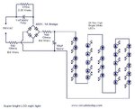
can any body help me out............
 
Last edited:

At a first approximation, 25 LEDs at 2V/LED = 50V. So with the LEds connected this will be the voltage at the output of the bridge. When the mains is at a peak, you get 230 X 1.4 ~ 331V . At the bridge input you will have your 50V + 1.6V (diode drop), so as mentioned you have a voltage drop of 279 and the main impedance is the cap (3K) so the current flowing through the circuit will be 93 mA (279/3 K).
Frank
 
I want to supplement chuckeys excellent explanation in a single regard. If the LEDs are white, as the schematic suggests, then the forward voltage can be rather expected around 3.5 V. So the LED current achieved with an 1 uF capacitor will be slightly smaller. Basically, you have to check the allowed current for your LED type (also considering self heating of the enclosure) and determine an appropriate capacitor. With white LEDs and the planned current level, I assume that nightlight will be sufficient for a large hallway!
 

You can do away with the plain diodes altogether. You also don't need the 10uF capacitor.

You can use the same operating method as with similar circuits using one LED and one diode, anti-parallel. Or two LED's, anti-parallel.

Consider creating two strings of LED's. Hook them up anti-parallel. One string will pass current one way to charge the capacitor. The other string will pass current in the other direction to discharge it.

Important: You should add a plain diode in each string, which has a high enough reverse V rating to prevent reverse flow through the LED's in a worst case scenario.

The LED's will flicker at 60 Hz. If it's unacceptable then disregard this post.

By the way conventional circuits show the limiting resistor having a higher value than 100 ohms.
 

my problem is i dont know at what voltage this leds glow,
.is rectifier ouput voltage(300 )correct output voltage giving ? if it is correct how can i reduce that voltage?..........

The high brightness LEDs that you usually have to use voltage drop of approx. 3.5V
Therefore, in the LEDs you will Vled = 24 * 3.5 = 84V

Due to the large difference between the line voltage and the output circuit behavior is similar to a current source, then don't worry about the output voltage without load.


As the average current that delivers this full-wave capacitive source is:


I = 4 f C Vpeak (1-Vout/Vpeak) = Isc * (1-Vout/Vpeak) * C [uF]
With Isc = 4 f = Vpk 65mA/uF to 230Vrms, 50Hz


So Iout = 65 * (1-84/325) * 1 = 48 mA


If your LEDs have rated this then you are OK, if not, you must modify the value of the capacitor series and probably the series resistance of 100 ohms (more watts) if you need more current.
 
  • Like
Reactions: Raza and FvM

    FvM

    Points: 2
    Helpful Answer Positive Rating

    Raza

    Points: 2
    Helpful Answer Positive Rating
The LED's will flicker at 60 Hz. If it's unacceptable then disregard this post.
Even more unwanted, operating the LEDs with a pulsating current reduces their efficiency and usable intensity.
By the way conventional circuits show the limiting resistor having a higher value than 100 ohms.
These resistors are only provided to limit inrush and voltage transient related currents. They are already dissipating about 1/4 W each. The main current limiting function is provided by the 1 u capacitor, as explained in other posts.
 
The 230VAC x 1.414=345VDC with a small 10ufd/400VDC as tank..For a string of 25LEDs with forward drop of 1.6VDC we get 40VDC
This gives a 300VDC to be used for the constant drive currents .Kindly choose an appropriate resistance .
I would suggest a IR540 mosfet with res. at gate to control the channel currents needed.
 
Status
Not open for further replies.

Part and Inventory Search

Welcome to EDABoard.com

Sponsor

Back
Top