Arrowspace
Banned
what is difference between Structural, behavior and test bench in VHDL?
Follow along with the video below to see how to install our site as a web app on your home screen.
Note: This feature may not be available in some browsers.
Code VHDL - [expand] 1 2 3 4 5 6 7 8 9 10 11 12 13 14 15 16 17 18 19 20 21 22 23 24 25 26 27 signal clk : std_logic; signal shift_in : std_logic; signal shift_reg : std_logic_vector(3 downto 0); -- assuming the existance of a d FF component s0 : dff port map ( d => shift_in, q => shift_reg(0), c => clk ); s1 : dff port map ( d => shift_reg(0), q => shift_reg(1), c => clk ); s2 : dff port map ( d => shift_reg(1), q => shift_reg(2), c => clk ); s3 : dff port map ( d => shift_reg(2), q => shift_reg(3), c => clk );
Code VHDL - [expand] 1 2 3 4 5 6 7 signal clk : std_logic; signal shift_in : std_logic; signal shift_reg : std_logic_vector(3 downto 0); process (clk) begin shift_reg <= shift_reg(2 downto 0) & shift_in; end process
Not sure this is as easy to do in VHDL. Verilog was designed to model transistor level logic. It includes as part of the language nmos, pmos, cmos, etc. It also supports 8 levels of drive strength from high impedance...to supply rail. I imagine by now someone has written a package that tries to address some of this for VHDL.i have done it using verilog. i think it is possible with vhdl alsoCan i do transistor level modelling in VHDL
Your CLA_Addr instance is incomplete, it ends on the line cout => cout, where is the closing );?
For a 4-bit shift register...
Structural modeling:
Code VHDL - [expand] 1 2 3 4 5 6 7 8 9 10 11 12 13 14 15 16 17 18 19 20 21 22 23 24 25 26 27 signal clk : std_logic; signal shift_in : std_logic; signal shift_reg : std_logic_vector(3 downto 0); -- assuming the existance of a d FF component s0 : dff port map ( d => shift_in, q => shift_reg(0), c => clk ); s1 : dff port map ( d => shift_reg(0), q => shift_reg(1), c => clk ); s2 : dff port map ( d => shift_reg(1), q => shift_reg(2), c => clk ); s3 : dff port map ( d => shift_reg(2), q => shift_reg(3), c => clk );
For behavioral modeling:
Code VHDL - [expand] 1 2 3 4 5 6 7 signal clk : std_logic; signal shift_in : std_logic; signal shift_reg : std_logic_vector(3 downto 0); process (clk) begin shift_reg <= shift_reg(2 downto 0) & shift_in; end process
Now which way is easier to see what is being implemented?
Not sure this is as easy to do in VHDL. Verilog was designed to model transistor level logic. It includes as part of the language nmos, pmos, cmos, etc. It also supports 8 levels of drive strength from high impedance...to supply rail. I imagine by now someone has written a package that tries to address some of this for VHDL.
Code VHDL - [expand] 1 2 3 4 5 6 7 8 9 10 11 12 13 14 15 16 17 18 19 20 21 22 23 24 25 26 27 28 29 30 31 32 33 34 35 36 37 38 39 40 41 42 43 44 45 46 47 48 49 50 51 52 -- TestBench Template LIBRARY ieee; USE ieee.std_logic_1164.ALL; USE ieee.numeric_std.ALL; USE ieee.std_logic_unsigned.all; ENTITY CLA_Adder_tb IS END CLA_Adder_tb; ARCHITECTURE behavior OF CLA_Adder_tb IS -- Component Declaration COMPONENT CLA_Adder PORT ( a, b: IN STD_LOGIC_VECTOR (3 DOWNTO 0); cin: IN STD_LOGIC; s: OUT STD_LOGIC_VECTOR (3 DOWNTO 0); cout: OUT STD_LOGIC ); END COMPONENT; SIGNAL a, b: STD_LOGIC_VECTOR (3 DOWNTO 0) ; SIGNAL cin: STD_LOGIC; SIGNAL s: STD_LOGIC_VECTOR (3 DOWNTO 0); SIGNAL cout: STD_LOGIC; -- Clock period definitions constant clk_period : time := 1 ns; BEGIN -- Component Instantiation uut: CLA_Adder PORT MAP( a => a, b => b, cin => cin, s => s, cout => cout); -- Clock process definitions( clock with 50% duty cycle is generated here clk_process :process begin clk <= '0'; wait for clk_period/2; --for 0.5 ns signal is '0'. clk <= '1'; wait for clk_period/2; --for next 0.5 ns signal is '1'. end process; END;
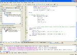
What are you expecting? And how do you propose to calculate the time it takes to perform an add with combinational logic in a functional simulation? Any timing delays in the code aren't synthesizable nor are they representative of the actual implemented design timing.Ok , my problem get solve , but new problem with that I want to calculate time consume by adder to perform full task , but my simulation window always showing 1us and multiple of 1us