alfhg
Newbie level 2

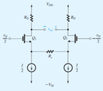
From Sedra & Smith, there is an NMOS differential pair in Fig.1, with a resistor Rs connected between the sources.
1. What's the effect of this resistor Rs?
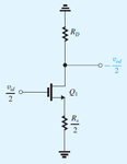
I think its small signal, differential "half circuit" should be Fig.2. So its effects should be improving linearity by reducing Vgs, higher bandwidth, at the price of lower differential gain?
Are there any additional effects of Rs?
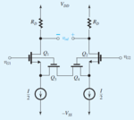
2. It also follows, Rs can be implemented using 2 FETs, as in Fig.3.
Are Q3 & Q4 NMOS or PMOS?
How does this circuit work, in both differential and common mode perspectives?
(As far as I can see, Q3 & Q4 do nothing in common mode, because the sources of Q1 & Q2 are at equal common mode voltage, so Q3 & Q4 are not conducting common mode currents.)
Thanks!


