Continue to Site

Welcome to EDAboard.com

Welcome to our site! EDAboard.com is an international Electronics Discussion Forum focused on EDA software, circuits, schematics, books, theory, papers, asic, pld, 8051, DSP, Network, RF, Analog Design, PCB, Service Manuals... and a whole lot more! To participate you need to register. Registration is free. Click here to register now.

What does it mean by " AK " (terminal or pin no on IGBT power module) ?

Status
Not open for further replies.

dineshdeshmuk

Full Member level 5
Full Member level 5
Joined
Sep 12, 2011
Messages
285
Helped
18
Reputation
36
Reaction score
18
Trophy points
1,298
Activity points
3,131
What does it mean by " AK " (terminal or pin no on IGBT power module) ?

I know that A is for Anode & K for Cathode ......... but what about AK ...... there is not any other pin or terminal having only " A " or only " K " ........

thanks
 

Markings of this kind are usually assuming knowledge of a device principle circuit. They are not primarly intended to support guessing about unknown components.

Nevertheless "AK" is almost self explanatory in my opinion. It can e.g. refer to the center tap of a half bridge, in other words a terminal, that's connected to both, anode and cathode.
 
This article uses the "A" to denote accessory connections to the emitter and collector:

http://www05.abb.com/global/scot/scot256.nsf/veritydisplay/01b51693ac3e10b4c1256c5600398aa8/$file/hk97ts_web.pdf

I tried, but could not find any current device from ABB that uses AK though, which would mean the accessory cathode based on that presumption. A top view picture of the device might help.

John

Edit: You may need to copy the link and paste it into your browser to see it.
 
Your example shows, that two letters can't tell much if you don't know what kind of device is connected to the terminals.

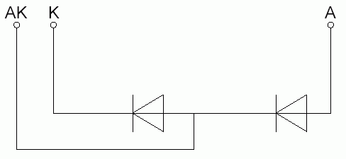
My favourite explanation is still the below scheme

100_1318630357.gif
 
Your example shows, that two letters can't tell much if you don't know what kind of device is connected to the terminals.

My favourite explanation is still the below scheme

100_1318630357.gif

part no. is cm40ye13-12h by Mitsubishi ....... its assembled inside G7 Yaskawa Inverter .....
there is not any circuit diagram on the case of this IGBT Power Module .......

SO, if i want to test that IGBT what should i consider about that terminal " AK " ?

thanks for your explanations though
 
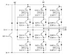
CM40YE13-12H
(Three Level Inverter) IGBT
40 Amperes/600 Volts

IGBTmod_CM40YE13-12H.jpg

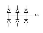
You should test like this diode combination
But note the effect of connected surrounding components

Diodes_AK_01.jpg
 
CM40YE13-12H
(Three Level Inverter) IGBT
40 Amperes/600 Volts

View attachment 62675

You should test like this diode combination
But note the effect of connected surrounding components

View attachment 62676

Should i test these diodes individually ?

https://obrazki.elektroda.pl/9_1318704616.jpg

To test this diode :

Connect Positive (Red) Probe to " AK " & connect Negative (Black) Probe to " E1U "
And, Connect Positive (Red) Probe to " E1U " & connect Negative (Black) Probe to " AK "

Is this Procedure right ?

And test Braking Circuit Diode as :

Connect Positive (Red) Probe to " P " OR '' AK " & connect Negative (Black) Probe to " B "
And, Connect Positive (Red) Probe to " B " & connect Negative (Black) Probe to " P " OR '' AK "

Is this Procedure right ?

Are P & Ak both short to each other ?

What is " RTC " ?

thanks bundle of
 
Should i test these diodes individually ?
Yes.

To test this diode :
Connect Positive (Red) Probe to " AK " & connect Negative (Black) Probe to " E1U "
And, Connect Positive (Red) Probe to " E1U " & connect Negative (Black) Probe to " AK "
Is this Procedure right ?
Yes.

And test Braking Circuit Diode as :
Connect Positive (Red) Probe to " P " OR '' AK " & connect Negative (Black) Probe to " B "
And, Connect Positive (Red) Probe to " B " & connect Negative (Black) Probe to " P " OR '' AK "
Is this Procedure right ?
No.
Test must do with P ( P and AK are are not connected )

Are P & Ak both short to each other ?
No.

What is " RTC " ?
Read part B. RTC Detection
**broken link removed**


Ref: another implementation of protective circuit NLU , look here...........


KAK
 
Last edited:
Yes.


Yes.


No.
Test must do with P ( P and AK are are not connected )


No.


Read part B. RTC Detection
**broken link removed**


Ref: another implementation of protective circuit NLU , look here...........


KAK

Difference between NLU & RTC ? (Any difference of application ?)

thanks a lot
 
Difference between NLU & RTC ? (Any difference of application ?)

Some IGBT modules have a built in RTC or NLU circuit connected between gate and emitter.
These circuits limits short circuit over current .
When excessive current flows in the device the RTC or NLU circuit activates and reduces
the gate voltage in order to limit the short circuit current.

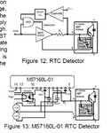
As above shown M57160L-01 hybrid gate driver circuit can implement RTC detection.

IGBTmod_RTC_detect.jpg
 
It's important to understand. that a NLU or RTC circuit in the IGBT module without a respective detection and shutdown feature in the driver just would delay wreck of the IGBT by a few 10 us. In my view, there's no functional or circuit difference between the shown NLU respectively RTC.
 

It's important to understand. that a NLU or RTC circuit in the IGBT module without a respective detection and shutdown feature in the driver just would delay wreck of the IGBT by a few 10 us. In my view, there's no functional or circuit difference between the shown NLU respectively RTC.

thanks a lot

so what do you wanted to explain would you elaborate more by saying " NLU or RTC circuit in the IGBT module without a respective detection and shutdown feature in the driver just would delay wreck of the IGBT by a few 10 us " ??
 
  • Like
Reactions: munzir

    munzir

    Points: 2
    Helpful Answer Positive Rating
Because current limit forces the IGBT into desaturated operation.
 
  • Like
Reactions: munzir

    munzir

    Points: 2
    Helpful Answer Positive Rating
Because current limit forces the IGBT into desaturated operation.

so it means you're saying that its not a good option (circuitry i.e. either RTC or NLU) to use these in a IGBT Power Module ???
 

Status
Not open for further replies.

Similar threads

Part and Inventory Search

Welcome to EDABoard.com

Sponsor

Back
Top