Continue to Site

Welcome to EDAboard.com

Welcome to our site! EDAboard.com is an international Electronics Discussion Forum focused on EDA software, circuits, schematics, books, theory, papers, asic, pld, 8051, DSP, Network, RF, Analog Design, PCB, Service Manuals... and a whole lot more! To participate you need to register. Registration is free. Click here to register now.

What correct inputs should be on this op amp circuit

Status
Not open for further replies.

karnel

Junior Member level 1
Joined
Nov 17, 2007
Messages
19
Helped
0
Reputation
0
Reaction score
0
Trophy points
1,281
Location
USA
Activity points
1,427
I have pair of op amp circuits which has to provide +0.4V...-2V at OUT#1 and +0.1V...+2V at OUT#2. Can somebody explain what correct input voltages(or currents?) has to be applied to IN1 and IN2 ? And how that circuits work?

Do I need any buf amp on inputs or I can just connect to DAC output directly?

I'm digital guy and analog is a dark area for me (shame).:cry:
 

you might want to give us a little more information about what this circuit is trying to do. The op amps with D1 and D2 are going to be highly non-linear. They might be acting like clamp circuits, although it is a pretty weird connection.
 

Hi,
for me is some illogic in these circuit; the one Op has a good voltage reference for the 2v threshold, the other a simple attenuator and at these is missed a min. 100 nF bypassing too...
K.
 

They might be acting like clamp circuits, although it is a pretty weird connection.
It's a usual clamp circuit, actually.
for me is some illogic in these circuit; the one Op has a good voltage reference for the 2v threshold, the other a simple
attenuator and at these is missed a min. 100 nF bypassing too...
Possibly yes, but it doesn't affect the principle circuit operation.

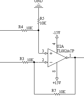
There's however a drawing error, I think. I would expect the first OP to form a differential amplifier. The correct circuit is below.

45_1265474839.gif


I also don't completely understand the voltage ranges written at the output. For one polarity, it indicates the exact clipping
level respectively, but for the other polarity, there is no clipping and the output voltage can be obviously much higher.
 

I'm redoing control of Microcannel Plate.Sorry for incomplete info, and yes it was error. I just finished fully redraw it. I'm reconstructing schematics from existing PCB. Here it is. It was part of big device which I dont know.

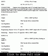
There is HV power supply with 2 outputs - one is +400V...-2000V and second +100V...+2000V. The voltage of each HV output is controlled by low votage signals OUT#1(+0.4V...-2V) and OUT#2 (+0.1V...+2V). So one volt of control signal equals to 1kV of HV. I know that from specifications of my HV PSU. In front of this HV PSU is this circuit borad, and I dont know what it does.

My goal is to develop FPGA based controller to connect to inputs of this circuit bard and control HV PSU. So I'm not sure what should I feed to IN1 and IN2 to have OUT#1(+0.4V...-2V) and OUT#2 (+0.1V...+2V) to go in to HV PSU.
 

Can you tell the type of your MCP, maybe send a datasheet pls?
Otherwise BE CARE WITH HV!!
If your input 220Rs are connected to/on HV: their TYPE IS VERY RELEVANT_must WITHSTAND for >=1-2KV:-(, or I CAN NOT SEE HOW IS YOUR ELECTRONICS ISOLATED FROM THE HV!!??...
Give us pls more details knowed...
K.
 

    karnel

    Points: 2
    Helpful Answer Positive Rating
I dont know what the MCP is here.
And no, this op amp circuit is not connected to High Voltages iteself. The outputs of this my op amp circuit (OUT#1) and (OUT#2) connetcs to a separete High Voltage PSU box. This box takes low voltages as a control signals. I just explained why so strange output voltages of my circut board should be. I need to feed something in to this circuit board which is in the middle betwen me and HV PSU box.
 

Obviously, it's a pure control circuit and not connected to HV. no circuit node could handle voltage levels outside
the +/- 15V supply range.

Within it's linear range, both circuits have simply a +1 gain from INx to Ex. The upper is clipping voltages below -2V and the
lower voltages above +2V. But they don't limit the other polarity. If you apply +10V to IN1, you get 10V at E4 (if the schematic
is complete). The OP in the clipper circuit is simply providing an ideal diode behaviour (near to zero voltage drop). The input
circuit is a simple differential amplifier. It's most likely used, because the external ground node (at IN1/IN2) exposes a voltage
difference to internal circuit ground or common mode interferences.
 

    karnel

    Points: 2
    Helpful Answer Positive Rating
It means is no mystery. I suspect diferential input should be more resistant to cable noise and ground loops. Right? My plan is to take simple Digital to Analog Converter controlled by FPGA and connect it directly to IN's.
 

Hey!
If you does plane to apply a DAC for driving these "special circuitry", why can you not think that voltage output DAC to apply as direct controller for the HV-Box inputs?
You dont need in my opinion, and for us knowed situation, a DAC + these OPs...
Only question is (bot not a problem) for cofigur the circuit; do you need a bidirectional control signal or only unidirectional?
K.
 

Yes, I'm thinking about this. My question is how much nose it coud apear in cable so dif amp might be of help there.

Another idea. I have a PLC which already has readily installed modules with 0..+10V outputs or also 4mA..20mA outputs. Do you think would it be possible to make some sort of circuit which woud take (0..+10V) or (4mA..20mA) input and give (+0.4...-2V) and (+0.1V..+2V) outputs?

In one case voltages are bipolar so will use +/-15 DC any way.
 

It means is no mystery.
Yes. Any kind of DAC can be used as setpoint source. The ranges can be adapted.

I didn't understand yet, if limiting for the other polarity is also required. One question is, if the original setpoint source
provided an additional limit or if it didn't. The other, if exceeding the range given in the schematic could harm the programmable HV source.
 

Can you place your DAC/or voltage output driver at (nearby) the HV unit?
Do you have some problem to transfer your controlling per parallel bits(flatcable)?
If you have these signal, it will be the simplest solution_and maybe the most reliable too...
How speedy must be your HV-controlling, then a PLC isnt very speedy?...
Induced noise in the control cable is for you at digital controlling the less interesting.
For me is the next one good the current loop & than diff /line receiver.
In all cases if you will built it up as "discret" circuit (External resistor at Diff-Amp): it will not have very good CMRR, than you can take some other circuit too, & their are more simple:)
In all variant of solution can you have trubles, especially GND loops etcetera...
K.

Added after 4 minutes:

@FvM,
HV converters are often "only control voltage followers", that is reason for some V upto +2V & some V upto -2V...
In my thinking is the lower voltage limit not so interesting, especially not the +0.4V for minus HV...
I mean: a normal voltageoutput DAC with 0...+2V & the other 0...-2V must be enough, but placed direct at HV-Unit_ are you on the same meaning pls?
K.
 

I dont know what behaviour of HV PSU would be if we set control volatge above +0.4V for OUT1 and below +0.1 for OUT2. But I believe nothing critical as it goes on lower bound. Possiblu it is limited inside HV box. Also it can be limited on my controller.

If I would go for PLC solution with 0..+10V . What modification is required to scale signal with 0.25 gain? I think some play with R3,R4,R5,R7. Aslo is it complicated to add 0.4V ofset?
 

Hi Karnel,
in my opinion, they are only a stypical specification & means: you can have the control voltage in the other direction too, but must be less as a diodes opening voltage!
K.

Added after 3 minutes:

I checked yet your beginings lines...
If you dont need a +400V HV in the -2KV part, you need only a control voltage from 0..+2KV!
The other polarity is simpler, then the HV was controlled only between +100V...2KV...

For me is clear, you need only 0..to + or - 2V ,if the MCP dont need to have up to +400v in the minus HV polarity.
K.
 

I'm afraid the oposite polarity of +0.4 can not be igneored as this MCP going to work with both - positive and negative particles (ions and electrons). So it might be reversible polarity is required.
 

Aha,
than is clear; build two bipolar DACs and these circuit (or some similar) for clamping garanted the ranges... (more simple components BOM:) and testing)
But tell me; is your HV supply garanted bipolar type?
K.

Added after 3 minutes:

In these case is better to forget the PLC & control it over (serial or parallel)bits from your Compi.
 

yes, there is HV box spcs:


If its only a smaller modul_I tink_ you must apply in the next slot in your crate a card with the OpAmps & DACs, be care pls with GNDs...
I think these modul isnt isolated, has the same GND as your complet electronics!
Eventuelly you will need a GND/Control signal separation? Analog Dev. has very good IsoDriver (on Silicon)...
K.
 

Status
Not open for further replies.

Part and Inventory Search

Welcome to EDABoard.com

Sponsor

Back
Top