NextEngine
Newbie level 4

Hello, I am trying to repair a Philips power board, it has some problems with its LED indicator, but it is not the point of this post.
When I open the shield, I find a little pcb with some discrete components on it. I guess its usage is to inspect the polarity of socket voltage and indicate the condition of lightening-proof.
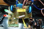
The picture following is an overview of the pcb.

There are two compnents I cannot identify.
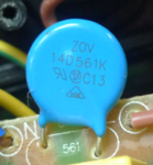
This is the first one, its designator is "UR1". What does "UR" represent? By the way, it will be good of you if you could provide information such as manufaturer, perhaps a datasheet would be the best.

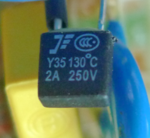
The second one is the following. Its designator is "F1", I guess it is a fuse. I have little knowledge of the manufaturer mark. Using google image search (searching by image) returns nothing valuable.

When I open the shield, I find a little pcb with some discrete components on it. I guess its usage is to inspect the polarity of socket voltage and indicate the condition of lightening-proof.
The picture following is an overview of the pcb.

There are two compnents I cannot identify.
This is the first one, its designator is "UR1". What does "UR" represent? By the way, it will be good of you if you could provide information such as manufaturer, perhaps a datasheet would be the best.

The second one is the following. Its designator is "F1", I guess it is a fuse. I have little knowledge of the manufaturer mark. Using google image search (searching by image) returns nothing valuable.


