Continue to Site

Welcome to EDAboard.com

Welcome to our site! EDAboard.com is an international Electronics Discussion Forum focused on EDA software, circuits, schematics, books, theory, papers, asic, pld, 8051, DSP, Network, RF, Analog Design, PCB, Service Manuals... and a whole lot more! To participate you need to register. Registration is free. Click here to register now.

What are Resolver, Encoder & Tachometer ? thanks in advance

Status
Not open for further replies.

phatcreators

Full Member level 5
Full Member level 5
Joined
Sep 2, 2011
Messages
315
Helped
24
Reputation
48
Reaction score
24
Trophy points
1,298
Activity points
3,458
What are Resolver, Encoder & Tachometer ?

Differences between these Feedback techniques ?

When to employ these ?

thanks
 

Resolver (electrical), a type of rotary electrical transformer used for measuring degrees of rotation
AMCI : Tech Tutorials : What Is A Resolver?

A rotary encoder converts rotary position to an analog (e.g., analog quadrature) or digital (e.g., digital quadrature, 32-bit parallel, or USB) electronic signal.
A linear encoder similarly converts linear position to an electronic signal.

Such encoders can be either absolute or incremental. The signal from an absolute encoder gives an unambiguous position within the travel range without requiring knowledge of any previous position. The signal from an incremental encoder is cyclical, thus ambiguous, and requires counting of cycles to maintain absolute position within the travel range. Both can provide the same accuracy, but the absolute encoder is more robust to interruptions in transducer signal.
AMCI : Tech Tutorials : What Is A Resolver?

A tachometer (revolution-counter, Tach, rev-counter, RPM gauge) is an instrument measuring the rotation speed of a shaft or disk, as in a motor or other machine.
servo motor tachometer
 
Last edited:
Resolver (electrical), a type of rotary electrical transformer used for measuring degrees of rotation

A rotary encoder converts rotary position to an analog (e.g., analog quadrature) or digital (e.g., digital quadrature, 32-bit parallel, or USB) electronic signal.
A linear encoder similarly converts linear position to an electronic signal.

Such encoders can be either absolute or incremental. The signal from an absolute encoder gives an unambiguous position within the travel range without requiring knowledge of any previous position. The signal from an incremental encoder is cyclical, thus ambiguous, and requires counting of cycles to maintain absolute position within the travel range. Both can provide the same accuracy, but the absolute encoder is more robust to interruptions in transducer signal.

A tachometer (revolution-counter, Tach, rev-counter, RPM gauge) is an instrument measuring the rotation speed of a shaft or disk, as in a motor or other machine.

In what conditions we do prefer any of these for feedback ?

for e.g : In what conditions we do prefer to use Resolver for feedback ?
In what conditions we do prefer to use Tachometer for feedback ?
In what conditions we do prefer to use Encoder for feedback ?

thanks for your reply
 
Modern tachometers are actually rotary incremental encoders which indicate position, speed, and direction of rotation.
Tachometer in older systems is usually small dc- or ac-generator indicating rpm.

Incremental Encoder
is an encoder that produces pulses in proportion to distance moved or rotated. Incremental encoders can also have a marker pulse Z, Z NOT (, ) once per revolution to provide a position reference. Avtron produces a full range of incremental rotary encoders.

Quadrature encoder
To determine which direction an encoder is revolving, encoders output quadrature signals: two streams of pulses, A & B, generated at 90° timing angles. (Also called A Quad B) A leading B indicates rotation in one direction; B leading A indicates the encoder is rotating in the opposite direction. Example: “A leads B with clockwise rotation as viewed from the encoder face on an M4 encoder.” Many encoders with quadrature outputs also have complementary outputs: A NOT and B NOT signals (, , , ).

Optical Encoder
typically uses a light source shining through, or reflecting off, an optical disk with lines or slots that interrupt the beam of light to an optical sensor. Electronics count the interruptions of the beam and generate the encoder’s output pulses.

Magnetic Encoder
Magnetic and magnetoresistive encoders typically use a magnetized rotor with north and south poles lined up around the perimeter of the disk. A magnetoresistive sensor detects the transitions, and these are the counts or pulses generated by the encoder. Magnetic encoders withstand dirt, dust, water, and temperature changes far better than optical encoders.

Tutorials Resolver Vs Encoder
Resolver vs Encoder

Application of Rotary Optical Encoders and Resolvers in Brushless Servo Motors
**broken link removed**

Encoders and Motor feedback systems
**broken link removed**

Position encoders
Position encoders

BML Magnetic Linear Encoder Systems
**broken link removed**

thanks a lot , but how to test (check) an encoder & a tachometer with DMM ? thanks
 

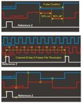
Determine Phase: A perfect Encoder should have a pulse output pattern like the one shown to the left.
When Channel A is on, Channel B should be on 50% of the time and off 50% of the time.

Count pulses: Pulses Per Revolution can be measured quickly. When the reference signal is received
the pulse counter starts then stops when the reference signal is received again.
This is useful when troubleshooting intermittent problems and damaged disks.
Can also be used on encoders with no reference signal.

Measure Voltage: When Channel A changes state, the meter measures the voltage of the Channel B pulse.
When reading a reference signal the voltage measurement is taken after a set period of time has
elapsed since the signal changed state.

Pulses can be 4......5000 pcs/360 degr.

This must be done with oscilloscope or best with special tester

from Universal Encoder Checker | test your encoder with confidence | Universal | Encoder | Checker | test | repair | check | calibrate | encoders |

Encoder_Output.jpg

Encorer output types:

Differential Line Driver Output

A differential output refers to the fact that each channel has a complement channel,
i.e. Channel A and Channel A not. A differential line driver is used to help increase noise immunity.
A differential line driver also allows you to sink or source more current then a Totem Pole output.
A differential line driver will work both with a sinking or sourcing circuit. It can also help in
increasing the distance in which a signal is transmitted.

Push Pull Output

A Push Pull output is an output that allows you to connect either a sinking or sourcing circuit.
This type of an output allows you to sink more current than a Totem Pole output and follow the input voltage.
A Push Pull output is chosen when an Open Collector output will not work with the controller that is
connected to the encoder

Totem Pole Output

A Totem Pole output is essentially the same as a Push Pull output; however, it is the terminology
commonly used when referring to a TTL device. The major difference between it and a Push Pull is
the amount of current that it can sink or source. The Totem Pole output is going to sink/source less
current then a Push Pull output is capable of sinking or sourcing. The other major difference is the output voltage between the two. The Totem Pole is a 5V DC signal only, where the Push Pull will follow the input voltage.

Open Collector Output

An Open Collector output is a NPN transistor. A NPN transistor allows the sinking of current to common.
It can be thought of as a switch that allows the circuit, after the load, to be connected to common.
This means that a source is required for the output to work. A supply through a load must be connected
to the output, otherwise the NPN transistor is simply creating a path to common, i.e. a dry contact.
Therefore, if you were to measure the voltage at the output of an open collector that is not hooked up
to some supply you would not see a change in voltage. The voltage should be measured across the output
load to determine if the open collector is working properly.

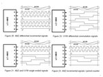
Quadrature output

Quadrature output refers to the fact that the signals A and B are separated by 90 degrees of phase shift
with A leading B or B leading A depending on the direction of rotation. It does not mean that the output
will be 4 times the amount of the Pulses Per Revolution of the encoder. The fact that the signals are 90
degrees out of phase enables the controller to determine the direction that the encoder is spinning.
You must use both the A and B signal to have a quadrature output and to get X2 or X4 logic

From rsdoran May 2nd, 2002, 08:03 AM PLCS.net Interactive PLC Talk Forum

Other output signal types:

Sine wave encoder

A variation on the Incremental encoder is the Sinewave Encoder.
Instead of producing two quadrature square waves, the outputs are quadrature sine waves
(a Sine and a Cosine). By performing the arctangent function, arbitrary levels of resolution can be achieved.

Absolute encoders

Traditional absolute encoders have multiple code rings with various binary weightings which
provide a data word representing the absolute position of the encoder within one revolution.
This type of encoder is often referred to as a parallel absolute encoder. (Serial data communication types found too)
The distinguishing feature of the absolute encoder is that it reports the absolute position of
the encoder to the electronics immediately upon power-up with no need for indexing.


Tachometer signal can be ac- or dc-voltage. Voltage must increase when rpm increases.
Signal must be proportional to rpm. (Measure voktage / rpm )

Tachometer signal can be also pulse train from magnetic sensor or encoder.
(Check as encoder)
 
Last edited:
iC-MH8
12 Bit Angular Hall Encoder with Sin/Cos Outputs


DESCRIPTION
The iC-MH8 12-bit angular encoder is a position sensor with integrated Hall sensors for scanning a permanent magnet.
The signal conditioning unit generates constant-amplitude sine and cosine voltages that can be used for angle calculation.
The resolution can be programmed up to a maximum of 4,096 angular increments per rotation.
The integrated serial interface also enables the position data to be read out to several networked sensors.
And the integrated memory can be written embedded in the data protocol.
The incremental interface with the pins A, B and Z supplies quadrature signals with an edge rate of up to 8 MHz.
Interpolation can be carried out with maximum resolution at a speed of 120,000 rpm.
The position of the index pulse Z is adjustable.
The commutation interface with the signals U, V and Wprovides 120° phase-shifted signals for block commutation
of eight pole EC motors.
The zero point of the commutation signals is freely definable in increments of 5.625° over 360°.
Sine and cosine signals are externally availabe to facilitate adjustement.
The RS422-compatible outputs of the incremental interface and the commutation interface are programmable
in the output current and the slew rate.
In conjunction with a rotating permanent magnet, the iC-MH8 module forms a one-chip encoder.
The entire configuration can be stored in the internal parameter ROM with zapping diodes.
The integrated programming algorithm assumes writing of the ROM structure.

SENSOR PRINCIPLE
In conjunction with a rotating permanent magnet, the iC-MH8 module can be used to create a complete encoder system.
A diametrically magnetized, cylindrical permanent magnet made of neodymium iron boron (NdFeB) or samarium cobalt
(SmCo) generates optimum sensor signals.
The diameter of the magnetshould be in the range of 3 to 6 mm.
The iC-MH8 has four Hall sensors adapted for angle determination and to convert the magnetic field into
a measurable Hall voltage.
Only the z-component of the magnetic field is evaluated, whereby the field lines pass through two opposing Hall
sensors in the opposite direction.
The arrangement of the Hall sensors is selected so that the mounting of the magnets relative to iC-MH8
is extremely tolerant.
Two Hall sensors combined provide a differential Hall signal. When the magnet is rotated around the longitudinal axis,
sine and cosine output voltages are produced which can be used to determine angles.

iC-MH8_encoder_01.jpg
iC-MH8_encoder_02.jpg
iC-MH8_encoder_03.jpg

More information.........
**broken link removed**
 

It looks like magnetic encoder are getting higher performance to compete with optical encoder in terms of resolution and accurracy. Here is an interesting apllication report comparing both for absolute encoder design: https://www.ichaus.biz/wp6_magnetic_vs_optical . Will be interesting to see who is winning this race.

Enjoy your design work!
 

Status
Not open for further replies.

Similar threads

Part and Inventory Search

Welcome to EDABoard.com

Sponsor

Back
Top