Continue to Site

Welcome to EDAboard.com

Welcome to our site! EDAboard.com is an international Electronics Discussion Forum focused on EDA software, circuits, schematics, books, theory, papers, asic, pld, 8051, DSP, Network, RF, Analog Design, PCB, Service Manuals... and a whole lot more! To participate you need to register. Registration is free. Click here to register now.

Welder SCR heat controller issues

Status
Not open for further replies.

tanky321

Member level 1
Member level 1
Joined
Jan 2, 2008
Messages
32
Helped
0
Reputation
0
Reaction score
0
Trophy points
1,286
Activity points
1,546
scr circuit welder

I came across a circuit online to vary the 220V input into a welder. This is done to control the amount of current entering the piece being welded, using a foot pedal. The circuit has worked for many people.

I built the circuit, but it doesnt work. R2 blew when I would crank the pot up, and there was no current entering the welder. I dont know if the SCR fired or not, but it wouldnt weld or make a spark what so ever.

My initial thoughts are that the circuit was designed for a particular type of SCR, and mine isnt compatible.

Also, im an EE student but im just starting out, I have some circuit theory under my belt, but im not sure on how to tackle this problem.

Can anyone help me out?

Sorry for the size of the pictures, but I wanted to keep the detail.

Thank you!
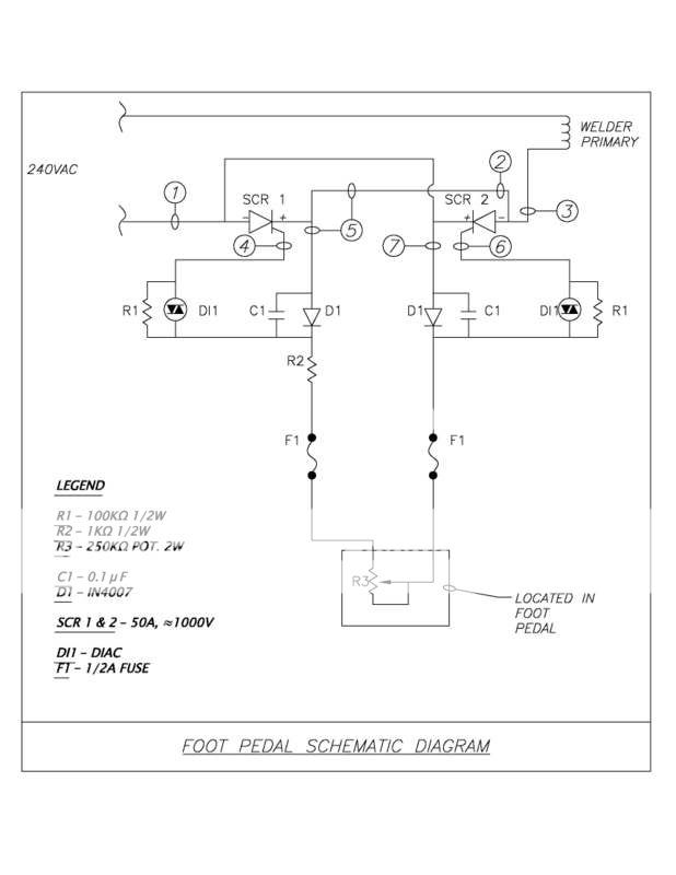
pedal.jpg

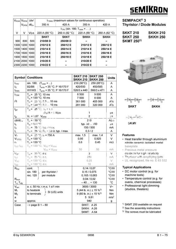
kt210_Page_1.jpg

skkt210-20e-semikron-thyristor-scr-skkt-210-20e-used.jpg

Board.jpg
 

heat controller +schematic

you have said R2 blew up when u crank up the pot.... r u saying that R2 got burnt up????
can you tell about the rating of R2, the pot used and the ratings of fuse used...
 

welder heat control

I think the issue is your SCRs. Their gate threshold current is 200mA. I believe the circuit was designed for SCRs with a much lower turn-on current. Power dissipated in R2 is I^2*R or (0.2)^2*1K = 40 W.

With such a high gate threshold current, Igt, the SCRs never get close to firing until you crank the pot way up. At that point, the current through R2 is too high and it burns up.

The whole purpose of R2, in my opinion, is to limit the gate current to the SCRs when the foot pedal is at its minimum resistance.

Based on the size of the foot pedal pot, I think the Igt of your SCRs is a couple of orders of magnitude too high. Please check the Igt spec of the SCRs that were originally called out in the schematic.
 

cd431260a-prx

There wasnt any type of SCR spec called out on the original schematic, all that was listed what that it needed to handle >50A and >600V.

Is there anyway I could adjust the value a componant to allow this circuit to work?

A member on another board said to replace the 1 diac with 2 in series, thus increasing their firing voltage.

Thanks
 

scr gate driver

Very large current SCRs usually require an active driver circuit, not the passive circuit you are using.

Take a look at:
**broken link removed**

This SCR is closer to the requirement and has a much lower Igt. I don't think two DIACs in series is going to help you. Think about Ohms Law. The SCR spec requires 200mA to trigger it. This current has to go through R2. Therefore, to keep R2 from burning up, you have to increase its wattage and decrease its resistance. Assume R2 is 1W, then the max resistance it can be is 25 ohms. This means you also have to reduce the value of the POT and increase its wattage. Probably a 5K POT is more appropriate at those currents. Wattage of the POT is harder to estimate because the duty cycle is minimal when the POT is at max resistance. Initial design was 2W, so I would at least double that.

These large current SCR packs are internally made up of several SCRs in parallel with a common heatsink. Each internal SCR needs a gate current and this parallel combo of gate currents is the problem. You can either keep the same SCR and radically modify the driver. Or, you can keep the same driver and get SCRs that are more appropriate.

Finally, to verify that the SCR is the issue, try to find someone else that built the circuit successfully and get their exact SCR part number. Then research this known working SCR and compare the specs, especially the gate drive current.
 
back to back scr gate trigger circuits

Hmm, so if I replace R2 with a high wattage resistor the circuit should work?

Using I²R=P it came out to (.200)(1000)=40W.

So if im understanding this correctly, using say a 1K 50W resistor this circuit should work?

Sorry if I sound like a complete retard, im still really fresh into EE so im not sure of everything.


What the other person was trying to tell me about the diacs was that they fire at 30V.
He said from the spec sheet that the gate resistance was 33Ω( which I dont see on the sheet). He then went on to say that 30V into the 33Ω didnt equal the 1A the SCR needed to trigger (which I cant find on the spec either). So by putting two in series it would increase the firing voltage to 60V and increasing the trigger current to 2A or so.
 

scr resistance welding

Sorry, but just replacing R2 with a higher wattage will not work. There are two reasons for this. First, lots of luck finding a 50W 1K resistor. Such a resistor would be physically huge!

Second, if you found such a resistor, the circuit would still not work because you would have NO adjustment range in the foot pedal. Let me explain why that is so. Remember that it takes 200mA to trigger the SCR. Assume that 30V is lost across the DIAC. Now lets calculate the circuit resistance needed to trigger the SCR at the very peak of the AC wave. Peak voltage is 1.414*RMS = 1.414*220 = 311 volts. (311-30)/0.2 = 1405 ohms. Therefore, the circuit resistance to just barely trigger the SCR is 1405 ohms. But 1000 ohms is in R2, which leaves only 405 ohms for the POT. Therefore, the useful range of the POT is from 0-405 ohms. This 405 ohms represents 0.16% of the POT actual sweep. Not much of an adjustment. This is why I previously recommended that you have to reduce the value of R2 and reduce the value of the POT.

I know you are looking for a quick easy fix. However, in my opinion, the SCRs are not well matched to the rest of the circuit and this is the real issue.

The DIAC's purpose is to cause a rapid voltage breakover that triggers the SCR at the same point on every cycle. This prevents the trigger point from wandering around as components heat up or age. Placing two in series does not increase the gate current, it reduces it!

One good way to diagnose circuits like this is to start with a small visual load. Replace the welder primary with two 100 watt 120V light bulbs in series, or a single high wattage 220 light bulb whichever is easier. Then the circuit becomes a lamp dimmer! If the issue is really the SCR gate current, then R2 should overheat and smoke just like the welder version. If R2 does not overheat and the POT can brighten and dim the lamps across a reasonable range of the POT, then the problem is not the gate circuit.
 
welder using scr current control

banjo wrote:
The whole purpose of R2, in my opinion, is to limit the gate current to the SCRs when the foot pedal is at its minimum resistance.

R2 is only limiting gate current to SCR 1 and not to SCR2.I don't see R2 limiting the gate current of SCR 2.If resistance before the fuse is use for limiting the gate current, there must be TWO resistors and not one, maybe the two SCRs are not of some voltage/current rating.

Added after 3 minutes:

@tanky321

Can you tell me what those circled number in schematic represents?
 

scr packs

@tanky321

Can you tell me what those circled number in schematic represents?

They dont mean anything, I just added that to the schematic so I could wire it up a little easier. Just as a reference for me.


Therefore, the circuit resistance to just barely trigger the SCR is 1405 ohms.

So if If I replace the pot and R2 with a value that works out to say 1500Ω that would work?

So maybe a 500Ω resistor and a 1K POT? I think the problem with that would be that I would be in the same dilemma of finding a 50W POT right?

Sorry if I sound like a meat head!

As far as a 50W 1KΩ though, I did find them, but your right their huge! 4" long or so!


Thanks for all your help guys.
 

foot heat control for arc welder

R2 limits the gate current of both SCRs. To see this, realize that all gate current for both SCRs must go through the POT. If it did not go through the POT then you would not have control of the circuit. Since R2 is is series with the POT, therefore it must be in the current path for the gate current of both SCRs. You can also see this by tracing through the circuit. However, you have to remember that the gate current for SCR1 is flowing in the opposite direction than the gate current for SCR2.

Lets calculate the result of a 500 ohm resistor and a 1K POT. For the circuit to work, we want full power when the POT is at minimum. Therefore, the only resistor in the circuit is the 500 ohms. Assume 30 volts across the DIAC and neglect the gate voltage for now. 500*0.2+30 =130 volts to trigger the SCR. The driving waveform from the power line is 311*sin(wt). However, since we want to know when in each cycle the SCR triggers, we replace (wt) with the angle X. 311*sin(x) = 130. Solve for X and you find that the earliest conduction angle is about 25 degrees. Therefore, you will conduct for a good portion of the cycle, but not exactly full power. This was a first-order approximation, so I neglected lots of stuff but it at least is an good estimate. (For your own amusement, repeat the calculations with two DIACs in series so that their voltage drop doubles.)

However, while the SCR will turn on through a reasonable range. The power dissipated in R2 and the POT is still very high. The real calculations would require you to integrate some chopped sine waves. Not too difficult, but rather than go through the bother, I will just use the RMS values. (220V -30V ) / 500 ohms = 0.38A (0.38)^2 * 500 = 72 Watts. Therefore, again, the wattage of the resistors is huge.

Using the original circuit and the original POT value, we can estimate the required gate current range. Assume that the POT is at max value and that we wnat the SCR to just barely trigger at the top of the AC waveform. This corresponds to 90 degrees and the 311*sin(90) = 311. (311-30)/251K = 1.1mA. Therefore, you would want an SCR with a Igt of 1mA to about 10mA max to work in this circuit. Since R2 is speced originally at 1/2W. Square Root (0.5/1K) = 22.4mA max gate current. Therefore, it would seem that the SCR parameters are 1000PIV, 50A, and less than 20mA gate current.
 
how scrs control welders

Ok I think i get it. So basically this circuit and this scr are a no go together.

I would really love to keep the SCR, its packaging and what not are convienient for the application, not to mention that I got a killer deal on it too.

What would the modifications to the circuit need to be? I guess il have to etch another board and what not.


Thanks
 

scr gate

I think that you have to check C1, D1 and the PCB trace for short circuit.
 

scr welder schematic

Tanky, this may help you. Oh, by the way hi everyone, 1st post here. I did some follow-up for you. A proven SCR for this circuit is the Powerex # CD431260A-PRX, 1200 v 60 A. The specs are available WWW for the life of me I can't get the link to work. This may help you. I am going to use the Semikron SKKT 56/16E, these specs are identical to the Powerex module. Have fun. Uncrichie.
 

skkt schematics

tanky321 said:
I came across a circuit online to vary the 220V input into a welder. This is done to control the amount of current entering the piece being welded, using a foot pedal. The circuit has worked for many people.

I built the circuit, but it doesnt work. R2 blew when I would crank the pot up, and there was no current entering the welder. I dont know if the SCR fired or not, but it wouldnt weld or make a spark what so ever.

My initial thoughts are that the circuit was designed for a particular type of SCR, and mine isnt compatible.

Also, im an EE student but im just starting out, I have some circuit theory under my belt, but im not sure on how to tackle this problem.

Can anyone help me out?

In my opinion, your schematic is fine, nothing is wrong in parts' values.

In fact, suppose the R2 has bad quality (in value or other matters) it cannot be blown out instantly when you switch on, but need a certain time. If your parts are good, it must conduct the current to the welder transformer before R2 being blown out. But, in your case during R2 is blown out, there is no current through SCRs, so the problems may go from PCB short circuit, or short circuited D1 diodes, diacs, C1 capacitors.

Just check your parts carefully.

nguyennam
 
+foot +control +pedal +circuit +welder

Hi,
The welder Primary takes in 240V 13A max. from a domestic power outlet.
I don't understand why you are using such a huge (and expensive) power device for control. The bulk of the power is delivered by the trafo inside the welder anyway.
Wouldn't a simple Triac or opto-Triac circuit (with a suitable rating) could do the job?
I hv an old 150A oil-filled welder which I intend to add a controller.

Keep on posting!
 

Hi ,

Can you please share the latest updated version of Welder SCR control ?

Is it possible to use this schematic for a 440volt also ?

Do any one have a Welder SCR control schematic that can be used on the Welder secondary side of the Transformer of 250 Amps ?

Thanks,

Regards,
John
 

So did anyone get this to work? or something similar and Dindeds did you ever get the controller you spoke of past the idea stage?
 

Edit: I just realised that this thread is years old apart from the last couple of posts, so this will probably be just circumstantial, I'll leave it here for anyone else.

I have a similar circuit on a stick welder that I converted to a tig, I also used an ignition coil resonant circuit to provide hf start, it works a treat.
I also used a semicron isomodule only mine unlike yours is a size1, yours is a size3 which is a little overkill.
Mine is a skkt 27b12 e, its rated at 27amps so eats 13a fuses on a 200 amp welder if I'm not carefull.
Trigger current is the issue as allready mentioned, larger thyristors need more current to fire yours being 200ma which is a lot, the one I use will fire with a multimeter set to ohms, so its a lot more sensitive than yours.
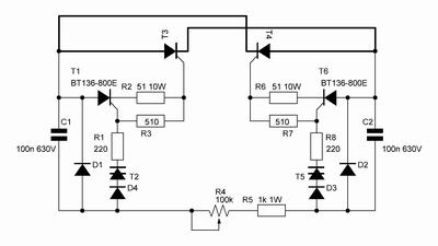
Deepones circuit looks as though it has a chance (I've talked with this guy before I think he knows his stuff), as it will provide much higher trigger current, I'm not sure if this circuit will like your original apply a negative bias to the thyristors when they are off, your original post circuit does and for a welder this is good, esp if it has hf start, however being a small 13a doemstic set it'll probably work well and you are stuck with the module now I take it.
Both circuits have designed in symmetry, meaning that the thyristors will fire at exactly the same voltage on the positive and negative side of the waveform, this is very important with a transformer as insymmetrical firing would case dc on the transformer and overheat it.
 
Last edited:

Status
Not open for further replies.

Part and Inventory Search

Welcome to EDABoard.com

Sponsor

Back
Top