neal.iweb
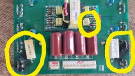
Newbie level 4

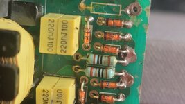
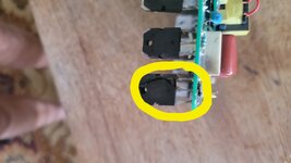
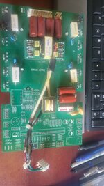
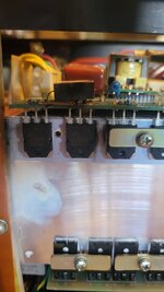
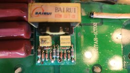
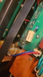
I have a project. I am a NOVICE. I would really appreciate obtaining guidance. The following is where I am with my project. I was given a multiprocess welder. It has a fried Upper Power Board. There are (2) two fried mosfets with part number K2837. There are also (2) two fried resistors. The resistor 5 color coded band indicates that they are 1.9 ohm 1/4W +/-0.25 tolerance resistors. I believe when the mosfets blew, they also cascaded destruction to the 66mmx30mm inverter board components. One of the 3k 1/4W +/-1% tolerance resistors was fried, along with a 1N48 Zener Diode with a marking of "C2", and I believe (2) two correcting capacitors with markings of 220nJ100 were also damaged (but I have not yet pulled those components), and possibly the transformer that is marked as Ei28 15:7. (Let me get back to that transformer at the bottom.) I may not have to rebuild the inverter board since there seems to be replacment boards available that match the solder pin points and dimensions.
The K2837 resistor through hole mosfet, is a very confusing part. It seems the data sheets I have found - well, many of the posted results I found after of an extensive Google search are confusing that part number with a 2SK2837 mosfet. There is only 1 replacement mosfet part I have identified which seems to be almost an exact match of its datasheet to the values I did find for the K2837 datasheets. Truly, I do not know which datasheets are correctly reporting the values for the K2837 parts. Of the datasheets I did find, which were NOT of the 2SK2837 part specs, the K2837 has higher Watt, Amps, and other aspects that make it seem to me to be NOT suitable or compatible for use in my welder.
The compatible part which I assume is a suitable replacement mosfet for the K2837 is part number FQA24N50. Please tell me if it is. I only can find what seem to be very minor differences when comparing the two datasheets, but again I am a novice and I do not know what is considered minor or not. The differences in the datasheets I found are showing the K2837 has Power Dissipation of 271W and the FQA24N50 has Power Dissipation of 290W. Is higher better, or could be detrimental for use in a welder? My concern is that if I purchase the FQA24N50 part, I do not know if I need to obtain 2 ohm or 1.9 ohm resistors, and I do not know what the additional Wattage would do to the other components. Other differences of these two mosfets is that the K2837 has Derating Factor above 25C at 2.22W/C and the FQA is at 2.33W/C. As a reminder, the current Upper Board has 1.9 ohm resistors.
For the other differences between the two mosfets, the Thermal Characteristics, are that the 2837 has .46C/W, and the FQA has .43C/W, and since this is a welder I am not certain if this Thermal Resistance Factor is significant or not. The only other last difference between the two mosfets are regarding the Static Drain Source On-Resistance. The 2837 is showing Typical as .16 ohms versus FQA as 0.156 ohm, and the Max for the 2837 is 0.19 ohm and the FQA is at 0.2 ohm. Other than as stated the data sheets are identical in every other value.
Is it safe to say that the FQA is an adequate replacement?
That inverter board transformer...a replacement for it, well an exact one doesn't exist anywhere I have searched. I can purchase new replacement inverter boards, but any that I have found which has E128 transformer are ONLY showing a label of 16:8. The inverter board components also have correcting capacitors labeled as part 224J100. I do NOT KNOW what those parts are in comparison to the 15:7 transformer and the correcting capacitors on my inverter board. I cannot see the Zener Diodes, but they do all are marked as the 1N48 series. Some of the inverter boards I found have PCB markings next to the Zener diodes on different boards as either being 3v3 or 5v1, which I know means the respective board is indicating a Zener of 3.3V versus 5.1V. I do not know the volts rating across the Zener Diodes on my fried inverter board, because I have yet to identify a DC power supply I can use to test voltages on the remaining working Zener diodes of that board. If I can identify a replacement inverter board which puts out the same voltage to the welder's front controller panel (which I believe is 24V, because all the Upper Boards I can find for every machine, puts out 24V to their respective front face panel controller board) then, I won't have to rebuild my inverter board and would just replace it. However, if I do have to rebuild it, I am wondering if the "C2" marking that I can see on the burned Zener, indicates 2V? Other Zener diodes on the inverter board are marked with a "5", but I have not removed them from the board yet to see the markings on the other diodes, or to test them.
My solution, is to go to aliexpress and find a board to harvest the components that I need. I have identified several that definitely have the same blue 1.9 ohm metal foil resistors. Again, though the inverter boards on those replacement Upper Boards look to have the same exact pin out, and likely are the same size where I could just resolder them onto my board, or use the parts to rebuild my fried parts, I do not know the voltages from the inverter I have, or what I would be getting in a harvested board.
Also, replacement Upper boards seem to come with a variety of mosfets. None of them have datasheets with specs as similar as the FQA24N50. The choices I have seen are K2837 (which I believe are all counterfeit and are likely the 2SK2837 mosfet "bait and switch" labeled as K2837, after I had one seller admit his K2837 mosfet were actually 2SK2837.) So, I want to stay away from them from any source. Other mosfets were, K3878, 23N50, 11N90, and 18N50. Some of those boards use 2 ohm resistors instead of the 1.9 ohm that are currently on my board. I do not believe there is a big difference in using either the 1.9 versus the 2 ohm resistors...but please correct me if any of my assumptions are incorrect.
My thought has been to buy a board with the 1.9 ohm resistors, and harvest them and their inverter board, and rebuild my board with those parts. I need advice if the FQA24N50 mosfet requires a specific resistor or can I use the 1.9 ohm or get a board with 2 ohm resistors, so I don't have to source individual components. If another type of resistor is more suitable for the FQA, which one?
If I can add pictures, I will have to edit this from my phone, to be able to add them from there.
I sure would appreciate any guidance which helps me get my welder working.
TIA.
Regards,
Neal.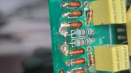


Last edited:

