Continue to Site

Welcome to EDAboard.com

Welcome to our site! EDAboard.com is an international Electronics Discussion Forum focused on EDA software, circuits, schematics, books, theory, papers, asic, pld, 8051, DSP, Network, RF, Analog Design, PCB, Service Manuals... and a whole lot more! To participate you need to register. Registration is free. Click here to register now.

Warning Buzzer Circuit for Redundant Power Supply

Status
Not open for further replies.

strape81

Junior Member level 3
Joined
Dec 16, 2011
Messages
25
Helped
2
Reputation
4
Reaction score
2
Trophy points
1,283
Visit site
Activity points
1,558
Hi all,

I need a warning buzzer circuit for a redundant power supply. The system is consisted of two power supplies (output: 12V) and after each power supply I use a decoupling diode. The buzzer will work when one the power supplies fails.

Please could you give me some ideas or a direction? If a circuit is available then I will be thankful.

Thanks a lot in advance!!!
 

very simple if you are using a dc source then just use a resistor and a not gate connected in parallel to the supply

the op of the not is coupled to a bell or warning led that will produce the required result
 

I recently had a requirement to do a similar thing (I wanted a buzzer to alarm if the primary power to my router died),
and in the end, I just went for something simple and super-old-tech - a non-rechargeable battery-powered buzzer. The battery will last for years,
and will sound an alarm for hours before it dies (my backup supply is non-rechargeable since it will be a rare ocurrence for me). This meets my needs perfectly.

The buzzer can be held in the 'off' position in any method you choose - e.g. a relay.
 

Thanks Jeffrey...I believe in simple, effective and reliable solutions too...

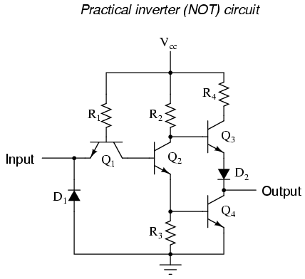
I have made a search and I could not find an IC that could fit my application. I need two NOT-Gates and the buzzer works at 12V/6mA. The voltage and the current specs could be found but the inverter ICs have usually 6 NOT-Gates which make them unattractive considering the costs. So I decided to search for a TTL NOT-Gate circuit and I found a the attached circuit.
Has somebody implemented that?
59_1346317563.png
 

Attachments

  • 04073.png
    04073.png
    5.7 KB · Views: 110

If you want the discrete device route, then this will work.
buzzer_holdoff.jpg
Replace R1 with your buzzer. When the 12V power is disconnected (e.g. via a switch) then the buzzer will sound.
A 12V buzzer should be fine running off 9V.
You don't need to use 9V, just make sure it is a value close to 12V, or a slightly lower voltage, for this circuit to work.
Or a single relay is cheap, if this is a 1-off circuit not for production.
 

Hello Strape,

I think this simple circuit will do the trick. Simulated it using Multisim and seemed to work fine. Just change the LED to a buzzer of your need. Hope this helps. :)

PSRedundancyBuzzer.png
 

Hello Strape,

I think this simple circuit will do the trick. Simulated it using Multisim and seemed to work fine. Just change the LED to a buzzer of your need. Hope this helps. :)

View attachment 79481

an excellent design but if you want individual alarms then use an OR gate instead of the AND gate
that should suit you
 

Yeah, I think if he wants an alarm for each power supply, then simply use an inverter for each supply so when either one goes low, one of the alarm will trip off. But if both power supply will be down, both alarms will sound.
 

Thanks a lot for your answers!!!

I have made two one-transistor-inverters and it works fine! Simple and reliable!!!
 

Status
Not open for further replies.

Similar threads

Part and Inventory Search

Welcome to EDABoard.com

Sponsor

Back
Top