visenri
Newbie level 2

Hello.
I've been hacking a hama IR universal remote because I want it to do some special things impossible with the original electronics.
Basically I'm going to reuse the PCB, buttons and housing and replace the microcontroller with a microchip PIC16, but i found something unusual in the keyboard matrix.
It uses a simplified charlieplexed keyboard that I would call Charlieplexed-light, because it uses the same concept but withoud diodes.
This reduces the total keys possible to half compared to the original charlieplexed design, but even then it's able to provide more keys than standard matrix keyboard.
In this case, using 9 microcontroller pins, 36 keys should be possible, but only 24 keys are really used.
Normally in a remote control like this I would have used a normal matrix and before entering the CPU in sleep mode I would set all columns to outputs (with low state) and configure all rows to trigger an interrupt on pin change (inputs with pull-up).
The problem is I can't do that with this keyboard design, because I can't find a static I/O configuration of the 9 pin to be able to wake up when any key is pressed.
The only way I can provide a similar functionality is to sleep, wake up every few ms and then scan the matrix to see if any key is pressed.
The fastest way (minimum number of wake ups per second) I found is a cycle of 3 scans setting to output low some pins and reading the rest.
I've not been able to do less than 3 scans to check if any key is pressed.
My question is:
Any idea to keep the CPU always in sleep like I use to do with the normal matrix keyboard? Or at least to reduce the number of scans? Remember that I'm not interested in knowing the exact key, just waking up the cpu no matter what key is pressed (later, when the cpu is running, it's no problem to scan the matrix as required to get the exact key).
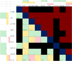
I've attached a file with a matrix diagram indicating the key combinations used:
Thank you in advance!
I've been hacking a hama IR universal remote because I want it to do some special things impossible with the original electronics.
Basically I'm going to reuse the PCB, buttons and housing and replace the microcontroller with a microchip PIC16, but i found something unusual in the keyboard matrix.
It uses a simplified charlieplexed keyboard that I would call Charlieplexed-light, because it uses the same concept but withoud diodes.
This reduces the total keys possible to half compared to the original charlieplexed design, but even then it's able to provide more keys than standard matrix keyboard.
In this case, using 9 microcontroller pins, 36 keys should be possible, but only 24 keys are really used.
Normally in a remote control like this I would have used a normal matrix and before entering the CPU in sleep mode I would set all columns to outputs (with low state) and configure all rows to trigger an interrupt on pin change (inputs with pull-up).
The problem is I can't do that with this keyboard design, because I can't find a static I/O configuration of the 9 pin to be able to wake up when any key is pressed.
The only way I can provide a similar functionality is to sleep, wake up every few ms and then scan the matrix to see if any key is pressed.
The fastest way (minimum number of wake ups per second) I found is a cycle of 3 scans setting to output low some pins and reading the rest.
I've not been able to do less than 3 scans to check if any key is pressed.
My question is:
Any idea to keep the CPU always in sleep like I use to do with the normal matrix keyboard? Or at least to reduce the number of scans? Remember that I'm not interested in knowing the exact key, just waking up the cpu no matter what key is pressed (later, when the cpu is running, it's no problem to scan the matrix as required to get the exact key).
I've attached a file with a matrix diagram indicating the key combinations used:
- The matrix shows each wire labeled with a color name (ORANGE, PINK, LIGHT-BLUE...up to 9).
- Dark red and dark blue indicate invalid combinations.
- Black cells show unused combinations.
- In each row-column I indicate with a 0,1 or 2 which signals are set at output low at each scan cycle.
- The valid cells have the color of the first scan that is able to detect that key (0 green, 1 yellow, 2 red).
Thank you in advance!
Attachments
Last edited by a moderator:
