Vermes
Advanced Member level 4


Volumer is a tool for remote control of the gain in two-channel audio track. Its destination is to work in a cascade connection with an analog preamplifier, made on rotary potentiometers. Remote control is done using the RC5 standard. Resistive divider formed by digital potentiometers MCP41010, controlled by interface SPI controls the gain. In addition, the device is equipped with a popular PCF8563 RTC with battery back-up. Supported by I2C,it extends the functionality of the device with time reading with one second resolution. You can also implement calendar and alarm. All settings data are available to the user via a standard, alphanumeric 2x16 display. The device has its own, independent, transformer power supply, and integrated relay allows you to enable/disable the main controlled power supply of the amplifier. The device uses Atmega8.
Digital potentiometers MCP41010 operate in circuit showed below:
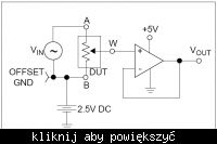
Useful signal must be within the limits of supply voltage span of potentiometers. In order to control the signal with zero constant component, the signal ground potential should be moved to half of the supply voltage of potentiometers. A detailed system of analog processing path, according to which PCB was designed in Protel 99SE, is shown on the following picture:
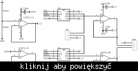
Except two digital potentiometers, there are two double operational amplifiers LM358. One is used as a pair of voltage followers, buffering outputs of the potentiometers, sensitive to too much load. The other one – one of the operational amplifiers was used to determine the ground signal potential 2,5V by the power ground. Another operational amplifier is not used and connected into a follower with the input on the power ground, in order not to arouse. LM358 are optimized to work with a single supply voltage, so they carry signals around 0V very well. Although when you want the followers operate well around 5V, you must provide supply voltage at least 2V greater. So the output followers are not powered from a stabilizer but voltage from behind the bridge, before LM7805.
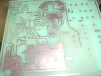
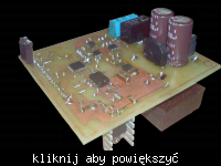
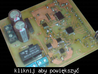
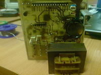

Schematic of the device in pdf and code in C (main function, files with libraries for support of RC5, SPI and I2C for Atmega8) can be found in the original thread.
Link to original thread (useful attachment) - Volumer (zdalna kontrola głośności/balansu) + zegar.
Last edited: