Continue to Site

Welcome to EDAboard.com

Welcome to our site! EDAboard.com is an international Electronics Discussion Forum focused on EDA software, circuits, schematics, books, theory, papers, asic, pld, 8051, DSP, Network, RF, Analog Design, PCB, Service Manuals... and a whole lot more! To participate you need to register. Registration is free. Click here to register now.

Voltage Supply PCB design

Status
Not open for further replies.

ginebra

Junior Member level 3
Joined
Mar 7, 2010
Messages
28
Helped
0
Reputation
0
Reaction score
0
Trophy points
1,281
Activity points
1,558
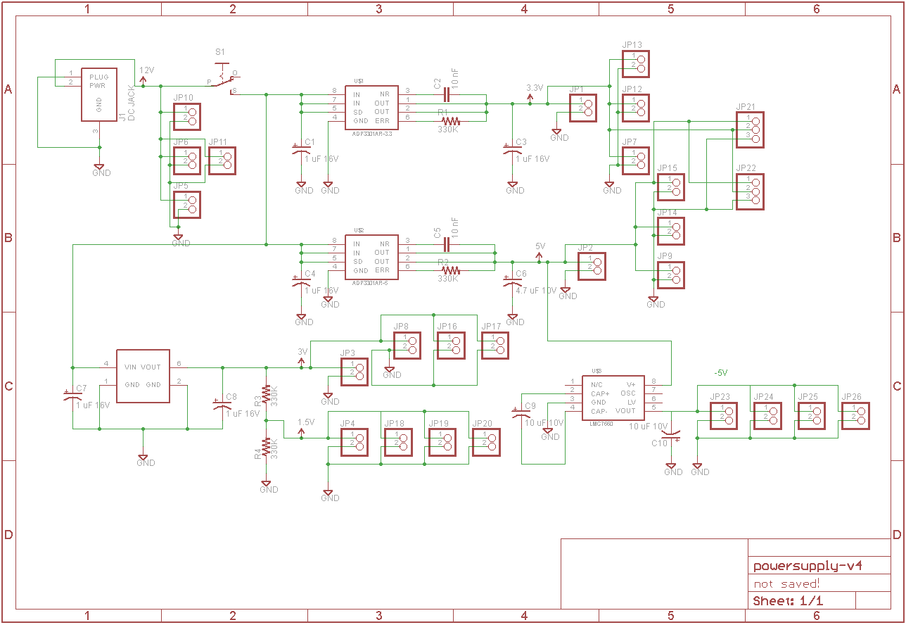
Hi I am designing a voltage supply PCB that would supply different voltages for the components I will use on a separate PCB. I will use a 12V 200mA AC-DC Adaptor as the main supply for this board and then convert it to the other voltages I need (5V, 3.3V, 3V, 1.5, -5V).

I would just like to ask if my design would work despite the numerous voltages needed to be produced. Thanks in advance.

Here is the schematic of my design:
 

The voltages may be correct but you wouldn't be able to draw current from the 1.5V outputs. A potential divider using high value resistors will seriously limit the available current and it will have no regulation.

Brian.
 
It would be helpful to know how much current your Power Supply will be required to provide at each of the output voltages before answering your question.

This is an unusual way of designing a Power Supply; I think most designers would choose to start with a transformer which provides the AC voltages which can be rectified and regulated down to the required output voltages. That is simpler, cheaper and should be more reliable in operation.
Its never good starting a PSU design from a single DC voltage when you want both positive and negative supplies !

However, to comment on your proposed circuit I think you must look again at the 1.5v output. You have a voltage divider of 2 very high value resistors (330k) to provide 1.5volts. But as soon as you draw any current from the 1.5v output, the load resistance will be in parallel with one of these resistors and will change the voltage division (and therefore will reduce the output voltage greatly).
We don't know what regulator you are proposing for the 3volt output but it is unlikely that you will need to use two seperate devices for the 3volt supply and another for the 3.3volt supply. A simple diode drop from a 3.3volt supply might be stable enough for a modest 3volt supply.

Please let us know the current requirements and if you could use a mains transformer with at least a centre tap.
 
You have used very high resistance in that divider, i suppose you would be able to use a voltage like that as a reference to an a/d converter but you should use lower resistors,
for example two 1K resistors would have a current flow of 3/2000=1.5mA.

Alex
 
Last edited:
Thanks all for your reply. The 1.5V has been removed from the design but I get your point.

Here are the devices that would be powered by this board via jumpers:

AD820 - maximum 800 uA quiescent current (12V)
ADF4108 - 0.4 mA max for Ip (Vp = 5V) and 17 mA max for Idd (Vdd = 3.3V)
HMC532LP4 - 3V @ 85 mA
HMC474MP86E - 3V requiring 25 mA
74hct04 - -5V supply with low power consumption of 20 uA max
TCXO - 2 mA max for 3V typical supply

Ideally the voltage supply board must power 2 sets of these devices. Is there something I should add or is the current configuration sufficient?

Thanks in advance for your advice.
 

Please note that many of the currents mentioned above are the current consumption of the devices with no load,
so for example when you connect something to the output of a "74hct04 - -5V supply with low power consumption of 20 uA max " the output can be many mA,
or the "AD820 - maximum 800 uA quiescent current (12V)" can give a 15mA output.

Alex
 
Status
Not open for further replies.

Similar threads

Part and Inventory Search

Welcome to EDABoard.com

Sponsor

Back
Top