A
ankushl
Guest

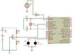
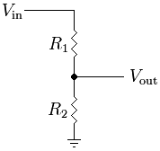
Hi...I am trying to make a circuit using PIC18F458...If the voltage falls below 4V, the LED should glow red, and if the voltage is above 4V the led should glow green...the problem is that the led always glows red. Two leds, one red and one green, are used. please help

#include<p18f458.h>
#include<delays.h>
#pragma config OSC=HS
#pragma config OSCS=OFF
#pragma config WDT=OFF
#pragma config DEBUG=OFF
#pragma config LVP=OFF
//Program to monitor battery voltage
//Port and pin definitions
#define voltage PORTAbits.AN2
#define red PORTBbits.RB6
#define green PORTBbits.RB7
void mydelay(unsigned char);
void main(void)
{
unsigned int h_byte, l_byte, byte_temp, adc;
float volt;
TRISAbits.TRISA2 = 1;
ADCON0 = 0x91;
ADCON1 = 0xC0; //all adc channels input
TRISB = 0x00;
red = 0;
green = 0;
while(1)
{
mydelay(1);
ADCON0bits.GO = 1;
while (ADCON0bits.DONE==1);
l_byte=ADRESL;
h_byte=ADRESH;
h_byte=h_byte<<8;
byte_temp=l_byte|h_byte;
//mydelay(1);
adc=byte_temp;
volt = (float)adc/204.6;
if (volt<4)
red = 1;
else
green = 1;
TRISAbits.TRISA2=0;
TRISBbits.TRISB7=0;
TRISBbits.TRISB5=0;
}
}
void mydelay(unsigned char val)
{
for(;val>=1;val--)
{
Delay1KTCYx(50);
}
}


