sabu31
Advanced Member level 1

Hi
I designed a boost converter operating at 50Khz,Vin=100-160V, Vo=400V,Ro=650-2450ohms, L=5mH,C=1mF.
Sensor gain is 1/715(using resistor divider 1M,6.8K given to an opam(voltage follower) and the output is filter throug R-C filter 560ohms,0.22uf and then given to adc channel of micro controller)
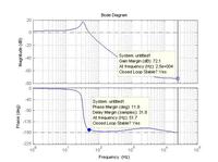
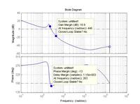
The closed loop controller( discrete) working in Matlab simulink is 16(z-0.99)(z-0.99)/((z-1)*(z-.1)).I am sampling at 2e-5 seconds.. This controller also works in actual hardware using dspic30f2020 microcontroller. Howver the when i check the bode plot of the compensated system, it shows unstable. How is it then working in simulation. If there was a modelling error then hardware and simulation should not match, but in this case ,hardware and simulation is working, but the bode plot is giving opposite answer.
What could be the reason for this.
Thanking you.


