[SOLVED] Voltage Follower Using OPA549 Not Working
- Thread starter hshah8970
- Start date
- Status
- Not open for further replies.

mister_rf
Advanced Member level 5

You need to provide a more accurate diagram to get an idea how you have it connected in the circuit. ;-)
The OPA549 is internally protected against over-temperature conditions and current overloads.
Have you tested the circuit with a resistive load?
The OPA549 is internally protected against over-temperature conditions and current overloads.
Have you tested the circuit with a resistive load?
hshah8970
Full Member level 2

Thank you for your response. I hope this helps:
The motor is connected with the output pins. The output pins (pin 1 and pin 2) are connected with each other and with with the negative input (pin 3).
The -Vcc pins (pin 5 and pin 7) are connected with each other and to -18V. These pins are also connected with Ref and Ilim pins (pin 6 and pin 8).
The +Vcc pins (pin 10 and pin 11) are connected with each other and with +18V.
The positive input pin (pin 4) is being given a voltage under 7V.
You will find that this is the correct configuration to get OPA549 into the voltage following configuration. And I haven't tested it with a resistor as the only yet, I shall do that tomorrow. But please provide me with your insight as to what could the problem be. Thank you.
mister_rf
Advanced Member level 5
The -Vcc pins (pin 5 and pin 7) are connected with each other and to -18V. These pins are also connected with Ref and Ilim pins (pin 6 and pin 8).
In the datasheet I have found the Ref and I lim pins are connected to the GND.
Second Motor wire to be connected also to the GND.
Attachments
-
 OPA549.png33.1 KB · Views: 402
hshah8970
Full Member level 2
Yes, of course I connected the second wire of the motor to the ground. I'm sorry I didn't specify that earlier.
And for maximum current output of the opamp, I thought the OPA549 datasheet read that Ilim should be connected directly to Ref and Ref should be connected directly to -Vcc. This is what I have done. I might be mistaken about this so I shall try grounding both pins tomorrow.
Could this be the fault?
And for maximum current output of the opamp, I thought the OPA549 datasheet read that Ilim should be connected directly to Ref and Ref should be connected directly to -Vcc. This is what I have done. I might be mistaken about this so I shall try grounding both pins tomorrow.
Could this be the fault?
- Joined
- Jan 22, 2008
- Messages
- 53,701
- Helped
- 14,811
- Reputation
- 29,919
- Reaction score
- 14,439
- Trophy points
- 1,393
- Location
- Bochum, Germany
- Activity points
- 303,603
Did you connect the current limiting resistor required by OPA549?
mister_rf
Advanced Member level 5
Try to monitor the ENABLE/STATUS (E/S) pin.
Also try to test by connecting Ref and Ilim to GND.
See also:
The Enable/Status Pin provides two unique functions: 1) output disable by forcing the pin low, and 2) thermal shutdown indication by monitoring the voltage level at the pin.
Also try to test by connecting Ref and Ilim to GND.
See also:
OUTPUT STAGE COMPENSATION
The complex load impedances common in power op amp applications can cause output stage instability. For normal operation, output compensation circuitry is typically not required. However, for difficult loads or if the OPA549 is intended to be driven into current limit, an R/C network may be required. Figure 8 shows an output R/C compensation (snubber) network which generally provides excellent stability…
Reactive and EMF-generating loads can return load current to the amplifier, causing the output voltage to exceed the power-supply voltage. This damaging condition can be avoided with clamp diodes from the output terminal to the power supplies,
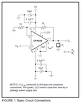
Power-supply terminals should be bypassed with low series impedance capacitors. The technique shown in Figure 1, using a ceramic and tantalum type in parallel, is recommended. Power-supply wiring should have low series impedance.
hshah8970
Full Member level 2
I shall be testing the circuit again in a few hours. Meanwhile, I would like to know the purpose of those capacitors in the figure that mister_rf attached. Are they there simply to minimize ripples in the opamp power source?
And FvM, I shall be connecting Ilim directly to Ref and then to ground. For maximum current output, the datasheet reads that the RCL resistor should be of zero value.
And FvM, I shall be connecting Ilim directly to Ref and then to ground. For maximum current output, the datasheet reads that the RCL resistor should be of zero value.
Last edited:
mister_rf
Advanced Member level 5
The additional bypass capacitors are necessary to improve the impedance of the power supplies. In this buffer amplifier circuit bypassing the op-amp power with a capacitor is a must. If the selection of the value of the bypass capacitor is an inappropriate value or placed too far from the power supply pin and not connected to ground directly on the PCB, the op-amp circuit may oscillate.
hshah8970
Full Member level 2
Ah! I swear these forums keep reminding me of what an electronics newbie I am!
Many thanks for your help, mister_rf.
And FvM, I read one of your comments regarding OPA series opamps in another thread; you mentioned that not all OPA series opamps can be used as buffers. Please help me in understanding this. How can I find out from the opamp's datasheet if OPA549 is a suitable buffering opamp? Which property should I be looking out for?
- Joined
- Jan 22, 2008
- Messages
- 53,701
- Helped
- 14,811
- Reputation
- 29,919
- Reaction score
- 14,439
- Trophy points
- 1,393
- Location
- Bochum, Germany
- Activity points
- 303,603
I didn't previously notice that you reported to have connected Ref and Ilim to Vs-. That's O.K. too and results in maximum (10 A) output current. So my question was superfluous. Connection of Ref to GND is mainly intended to allow the control of the E/S pin with ground referenced logic.I shall be connecting Ilim directly to Ref and then to ground. For maximum current output, the datasheet reads that the RCL resistor should be of zero value.
mister_rf
Advanced Member level 5
The Bode plot is also useful in determining stability, you may read here more details:
https://www.analog.com/static/imported-files/tutorials/MT-033.pdf
- - - Updated - - -
Usually a target phase margin of 60° is highly desirable in feedback amplifier design as a tradeoff between loop stability and settling time in the transient response. Typically, the minimum acceptable phase margin is 45°. In this situation we get a phase margin > 60° and that’s OK.
https://www.analog.com/static/imported-files/tutorials/MT-033.pdf
if the closed-loop gain (noise gain) intersects the open-loop gain at a slope of greater than 6 dB/octave (20 dB/decade) the amplifier may be unstable (depending on the phase margin).
Feedback stability theory states that the closed-loop gain must intersect the open-loop gain at a slope no greater than 6 dB/octave (single pole response) for the system to be unconditionally stable. If the response is 12 dB/octave (two pole response), the op amp will oscillate. The easiest way to think of this is that each pole adds 90° of phase shift. Two poles yields 180° phase shift, and 180° of phase shift turns negative feedback into positive feedback which means oscillations
The question could be asked—why would you want an amplifier that is not unity gain stable? The answer is that for a given amplifier, the bandwidth can be increased at higher gains if the amplifier is not designed to be unity gain stable. This type of op amp is sometimes referred to as a decompensated op amp. However, the stability criteria still must be met. This criteria is that the closed-loop gain must intercept the open-loop gain at a slope of 6 dB/octave (single pole response). If not, the amplifier will oscillate. Decompensated op amps will therefore only be stable at higher gains which are specified on the data sheet.
- - - Updated - - -
Usually a target phase margin of 60° is highly desirable in feedback amplifier design as a tradeoff between loop stability and settling time in the transient response. Typically, the minimum acceptable phase margin is 45°. In this situation we get a phase margin > 60° and that’s OK.
Attachments
hshah8970
Full Member level 2
Hello again! First of all, many thanks for your previous help. I made the necessary fixes and tried my voltage follower at various resistive loads and it worked flawlessly. However when it comes to my DC motor, which is an inductive load, the opamp begins to oscillate - I am guessing this based on the fact the motor stops and my opamp heats up a lot.
Could you suggest any solutions to this? I did a bit of online reading and concluded that connecting a resistor in series before the motor could help; I have yet to test this though (testing will be done on Tuesday). But I would prefer some other solution, if possible, since the power dissipated by the resistor is undesirable - I want all the power to be consumed by the motor.
Could you suggest any solutions to this? I did a bit of online reading and concluded that connecting a resistor in series before the motor could help; I have yet to test this though (testing will be done on Tuesday). But I would prefer some other solution, if possible, since the power dissipated by the resistor is undesirable - I want all the power to be consumed by the motor.
- Joined
- Jan 22, 2008
- Messages
- 53,701
- Helped
- 14,811
- Reputation
- 29,919
- Reaction score
- 14,439
- Trophy points
- 1,393
- Location
- Bochum, Germany
- Activity points
- 303,603
I don't see why an inductve load should cause oscillations, it can be rather expected for capacitive loads. May it be the case that the motor has interference suppression capacitors connected in parallel?
hshah8970
Full Member level 2
Precisely. I did a bit of reading and understood that inductive loads increase the phase margin which might actually make the whole thing more stable (please confirm). As for the capacitors, there are none such attached.
- - - Updated - - -
Did more reading. Does the motor send back current through the line towards the amp through back EMF? Can connecting a large capacitor in parallel be a possible solution?
- - - Updated - - -
Did more reading. Does the motor send back current through the line towards the amp through back EMF? Can connecting a large capacitor in parallel be a possible solution?
mister_rf
Advanced Member level 5
Bypass capacitors provide a low impedance to AC signals on the power lines. The objective is to eliminate the effects of the power bus inductances and resistances so that transient currents flowing across the power bus do not cause excessive noise at the power and ground pins of the IC. The bypass capacitors should have low effective series resistance (ESR) and series inductance while having a large enough capacitance value to supply current to the IC during switching. In order to achieve this we use two capacitors for bypassing: a large cap (nominally 10uF-47uF) for low frequencies, and a small cap (nominally 0.1uF) for high frequencies. The need for multiple capacitors comes from the parasitic associated with real capacitors.
hshah8970
Full Member level 2
I'm marking this thread solved and continuing the discussion here: https://www.edaboard.com/threads/256067/
I apologize for mistakenly splitting the discussion into two threads.
I apologize for mistakenly splitting the discussion into two threads.
- Status
- Not open for further replies.