Continue to Site

Welcome to EDAboard.com

Welcome to our site! EDAboard.com is an international Electronics Discussion Forum focused on EDA software, circuits, schematics, books, theory, papers, asic, pld, 8051, DSP, Network, RF, Analog Design, PCB, Service Manuals... and a whole lot more! To participate you need to register. Registration is free. Click here to register now.

Voltage drop of vacuum tube diode when used as HF detector?

neazoi

Advanced Member level 6
Joined
Jan 5, 2008
Messages
4,134
Helped
13
Reputation
26
Reaction score
15
Trophy points
1,318
Location
Greece
Activity points
37,023
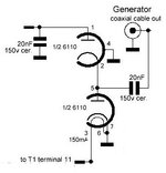
What is the voltage drop of this Tek vacuum tube negative output detector, when used on HF?

Should I expect lower voltage drop than germanium diodes, and how much roughly?

Also, what is the maximum input voltage peak to peak that I can apply to the input of this detector?
 

Attachments

  • detector.JPG
    detector.JPG
    23.9 KB · Views: 54
  • 6110.pdf
    488.1 KB · Views: 37
Last edited:
My guess, these are the relevant spec's.
1. 10 Vdc no
2. 150 Vac
View attachment 192858View attachment 192860
For 1, it is definitely not 10Vdc, since this would be totally useless as a detector. The current defined in the datasheet is 15mA, but as a detector driving a VTVM grid, the current should be much much less, so the voltage drop much much less, but I do not know if this is lower than Ge diodes or not.

For 2 is it VAC peak to peak, or RMS, or peak?
 
This sort of gives you an indication :

1722801844038.png


I suspect all V's in avg DC.....

Odd data for a detector seems missing, eg. small signal in depth data, given tube diodes
used extensively in communications receivers of yore.....
 

    neazoi

    Points: 2
    Helpful Answer Positive Rating
Odd data for a detector seems missing, eg. small signal in depth data, given tube diodes
used extensively in communications receivers of yore.....
Exactly, that's my point. The small signal characteristics, especially the voltage drop
 
Need to know load resistance to determine voltage drop. A first order estimation of Uf versus If according to datasheet is resistive (about 1k), zero threshold voltage. For high load impedance better than Ge diode (100 - 200 mV threshold).

Fullwave rectifier (similar to your circuit) maximal input voltage is specified with 150 V.
 

    neazoi

    Points: 2
    Helpful Answer Positive Rating
Exactly, that's my point. The small signal characteristics, especially the voltage drop
The above tube VI plot demonstrates the useful voltage above 0.5V to 30V. requires much more voltage gain before detection than a semi. diode.

Modulation of the carrier of a Hot carrier = Schottky diode or Ge diode linearity is good above 150 mV and up with a "knee" voltage 200 ~250 mV depending on max current. at max. modulation .

https://tinyurl.com/23slmaks <== sim.

Here with a sweep from 0 to 600 mV using an offset triangle wave from a voltage source into 1k load and 11 uA of current with 237 mV of detected signal.

For linear modulation detection, one can linearize the diode by choosing a bias current that makes the dynamic diode resistance far lower than the load.
For peak power detection, one can use a directional coupler or splitter to measure low levels of reflected signal or a fraction of the output power into a small C load.

1722810608053.png


The plots above show the shape of a 0 to 600 mV sweep with a triangle to show the square law current response and the effective linear region where the load resistance is much greater than the diode dynamic resistance. The voltage required is far lower with diodes although similar power levels of input signal while noise is another factor.
--- Updated ---


You may not think this is a fair comparison using these Si Sch.(2N5717),
but the Ge diode (1N34) load (2.2 M) must be far greater than the 1K Sch. diode load,
for the same peak input v and output > 240 mV. approx.

This shows the benefit of the better conductance of the hot carrier or Schottky diode.
1722811877941.png

--- Updated ---

When choosing VHF UHF detector diodes, one looks for the lowest C (0V) occurring naturally in the lowest current-rated diodes and the lowest forward voltage Vf at the desired Tau= RC load line and thus desired current and load R.

Lower impedances are generally preferred to reduce stray noise but are design choices.

1722812865295.png
 
Last edited:

    neazoi

    Points: 2
    Helpful Answer Positive Rating

LaTeX Commands Quick-Menu:

Part and Inventory Search

Welcome to EDABoard.com

Sponsor

Back
Top