voxmagna
Newbie level 6

I often need to split voltage rails for a center rail virtual ground cheap and simple. I'm working with op amp circuits running from battery 4-6 Volts. I took several different op amps from my components stock, bread boarded split rail circuits and learned a lot:
1. The output current can be just a few mA, or some opamps can do 30mA.
2. Some op amps are unstable with a capacitor load on the split rail output
3. The output current into a resistor load isn't always symmetrical sinking to ground or sourcing current from the supply rail.
4. The quiescent current draw of some opamps can be over 3mA, too high for low power battery designs.
5. Adding a BJT output driver with diodes and resistors for more currrent, increases the complexity and parts count.
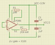
I've tested an unconventional design using an LM386 audio amp IC. It's not an op amp in the normal sense and only has a gain of x20, but it can drive 8 ohm mini speakers or headphones with capacitor loads. It's an old chip with not much in it, but easily sourced cheap. It's capable of X200 gain but that's a.c gain and I wanted higher d.c gain for rail spliting to hold the rail voltage constant at VCC/2 up to 100mA output.
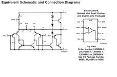
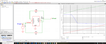
I studied the LM386 architcture and bread boarded it as a rail splitter, testing with a dvm, 'scope for noise, capacitor loads and resistors. Without any aditional parts, it would rail split but had a -250mV offset from center and some voltage variation with resistor test loads when sinking and sourcing current up to 150mA. I studied the LM386 nternal schematic and calculated I could replace the gain capacitor on pins 1 & 8 with a 180 ohm resistor to increase gain from x20 to X100. The fixed offset voltage of VCC/2 -250mV was still present, but I could correct this with an external resistor 91k on pin 7. All my practical tests seem to show this works with 5 parts. Can anybody see the downside because I've not seen anybody do this? Thanks


