Vermes
Advanced Member level 4


It is a remake of the game Tetris. VGA monitor was used as the LCD display and pad from Pegasus as the controller.
Parameters:
- Processor: Atmega8 (8kB flash, 1kB SRAM)
- Image: 104x120px, 16 colours
- Input: Pad from Pegasus (8 buttons)
- Sound: Mono, generated by the PWM
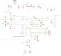
Processor used was Atmega8 clocked with a frequency of 20MHz. The processor operates really stable at this frequency. 90% of the processor time is devoted to the generation of VGA image. Generating line is very sensitive to delays. Therefore, each line is generated in the 16bit timer interrupt induced exactly each 636 clock cycles. Synchronization and colour signals are set there. For this reason you cannot use other interrupts in the console. The image is 16 colours, generated by resistor dividers. Graphics is generated, collisions and the whole game logy are calculated in 10% of the processor time. The device is powered by the stabilizer 7805 in the standard configuration.
Sound:
Mono sound is provided to the project, a connector is derived together with the filter and divider.
Software:
The whole software was written in Assembler, because Atmega8 has only 1kB of RAM and it is too little to generate a nice image. Writing in Assembler provides additional control. While writing, you can base on Tengen Tetris and Tetris for Gameboy. The principles are quite the same. The EEPROM is used to store the best results obtained in the game. ADC was used to draw blocks. Noise is read from one of the pins. Sources are attached in the annex.
Generating image:
To generate VGA image (640x480), you need the frequency of 25.175MHz – one clock cycle is one pixel. It is not easy to get the crystal and the frequency could turn out to be too high to proper operation of the processor. Crystal 20.000MHz is easily available, but using it would decrease the resolution to 512x480. Generating each line looks like this: by 512 cycles (for 25.175MHz quartz it is 640 cycles), the next colour is thrown each cycle. Unfortunately, it is impossible for this microcontroller, because the same load data from SRAM takes two clock cycles, and the instruction OUT (ejection data to the port) – 1 cycle. So, at best, you can get 512/3~170px. Then, by 124 cycles you need to generate horizontal sync signals. Here you can go to interrupt, cast registers onto the stack, set the synchronization, check, which line is being rendered now – if greater than 480, get out of the break and give the time for the rest of the program to the processor. Image is generated by 480 lines, then by 11 lines the black colour is displayed, and after that within 2 lines the vertical synchronization is set and for the next 31 lines there is still dark. This gives you 44 lines, by which nothing is done. This gives (roughly) 512*44=22528 free processor cycles. The rest of the program is executed at this point. Unfortunately, if you do not have that amount of RAM, you have another way to generate nice image. The best idea is to divide the memory to tiles of size 4x4 pixels. 28X30 such tiles fit in the memory. One tile is one of 256 images stored in flash. In this way, you can easily draw blocks and fonts.
In the video interrupt the individual tiles values are converted to values found in flash. Unfortunately, these calculations take much (up to 19 cycles), which significantly reduces the resolution. The result is a resolution of 104x120 pixels.
Calculated pixels are thrown to PORTC, where three youngest bits are RGB colours and the fourth bit is a bit of brightness. It is connected through the diodes and resistor to each of the RGB bits. When it is not lit – on every bit there is 0V, and when turned - 0.35V (grey). This increases the number of colours from 8 to 16.
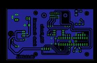
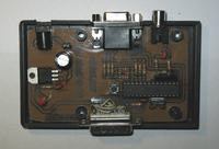
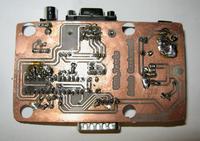
The board was made by thermal transfer method. Connector of the pad is connected by headers.
Description of the pad's outputs: http://nesdev.parodius.com/ffpa.txt.


Link to original thread (useful attachment) – VGA Tetris - projekt na konkurs Gra Retro