Continue to Site

Welcome to EDAboard.com

Welcome to our site! EDAboard.com is an international Electronics Discussion Forum focused on EDA software, circuits, schematics, books, theory, papers, asic, pld, 8051, DSP, Network, RF, Analog Design, PCB, Service Manuals... and a whole lot more! To participate you need to register. Registration is free. Click here to register now.

Very Sensative AC finder circuit my design

Status
Not open for further replies.

dom444

Junior Member level 2
Joined
Jul 9, 2009
Messages
23
Helped
0
Reputation
0
Reaction score
1
Trophy points
1,283
Location
Australia
Activity points
1,462
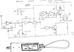
this is my personal design for a sensitive ac mains finder circuit this one is unique from anything that i have seen out there, you can very the sensitivity from touching the wire to picking up hum from 2 meters away or finding
cables through walls, it has a green led when powered up that goes red when picking up, it also gives an audible hum from the peizo has a pinpoint button and sensitivity control. I will post a vid when i can get a chance to make it
important will not work with all 4069 ic's I have to find my prototype and will let you know the markings. this is better than anything commercially out there and was inspired from the fact my son almost killed himself as a apprentice electrician while in a roof space.


img002.jpg
 
Last edited:

2 metres is a remarkable range !! Is that 'front end' a low-pass filter ?

I ask as I use a budget commercial 'volt wand', often have to do some waving and back-tracking to figure which of several adjacent wires is which.

One head-scratcher was due to tracking in a damp attic, so that if adjacent room's lights were on, a room's LED lamps would blink every 10~20 secs though switched off. Although the creepage did not give a shock hazard, *all* the wiring tested live with the volt wand. Poking in a 'neon' tester told a different story.

FWIW, improving the ventilation resolved the problem...
 

2 meters is right no exaggeration front end is high impedance low pass filter you get an audible hum not a random beep so easy to discern what you are picking up, the 100k pot in series with the 27k sets the sensitivity and i have built 4 versions of this unit all work as described. only thing is the 4069 chip as i said can't remember if was buffered or unbuffered version have to find it i know one version does not work.
 

I have found one of my prototypes with a 4069UB you get very modest range much like the commercial finders except still a lot better range is 6-12" but with the chip marked CD4069BE you get this remarkable range the sensitivity in a room has to be kicked right back as the RED LED is constantly on from cable hum from the house wiring. the difference between chips is like using a superhet receiver compared to a crystal set.
 
Last edited:

I looked for a datasheet for a CD4069BE and a few places said they have it but it is actually an ordinary CD4069UB datasheet.
Amazon will sell you some Texas Instruments CD4069BE with a photo of it but Texas Instruments website never heard of it. Cheap Chinese fakes?
 

yes they are hard to find and they are Chinese IC's I got mine from Ali-express about 100 very cheap a few years back you have to be specific as they send you the 4069UB all the time, this is one chip the Chinese do better for this purpose.

I am having 100 PCB's made up at the moment as i intend to sell the boards or kits on ebay when organized.

- - - Updated - - -

this is my layout

power wand.jpg

- - - Updated - - -

better schematic

power wand.JPG
 

The minimum supply voltage for a CD4069 is 3V but the battery drops to only 2V as it runs down.

You show an upside down PNP transistor for T2. It is labelled MPS42 which does not exist. There is a 300V MPSA42 NPN transistor available that will not work as T2 in that circuit but the 300V rating is not needed to drive a simple piezo.
Like T1, a BC557 PNP transistor will work if it connected like I show it.

Is the piezo a beeper with its own built-in oscillator or is it a piezo transducer? If it is a transducer then is your oscillator frequency the same as its resonance?
 

Attachments

  • Power Wand.png
    Power Wand.png
    60.5 KB · Views: 195

Sorry guys this is it now I have checked it again the MPS42 is used because the 22mh induct Causes high voltage spikes that amplify the output on the piezo transducer its an old method of getting more volume from a piezo. I had it marked as a PNP transistor somehow missed it the reason for using the PNP like that at T1 is the led will stay red if you use a NPN as it needs the negative going signal after the inverters to turn the LED on. 3V works fine for this as it uses very little current in use and should last a long time/

power wand.JPG

- - - Updated - - -

the Transistor is marked MPSA42 high voltage NPN
 
Last edited:

The base-emitter voltage drop of only 0.7V of the MPSA42 will stop the output of the oscillator without having a series base resistor.
 

As you can see in my Video clip mine is working fine and so are the other 5 proto's i have made you can put one in if you like some of the way this is designed is from reverse engineering commercial ac finders they do not use a base resistor on there's so i didn't to save part count but works anyway.
 
Last edited:

Status
Not open for further replies.

Similar threads

Part and Inventory Search

Welcome to EDABoard.com

Sponsor

Back
Top