Continue to Site

Welcome to EDAboard.com

Welcome to our site! EDAboard.com is an international Electronics Discussion Forum focused on EDA software, circuits, schematics, books, theory, papers, asic, pld, 8051, DSP, Network, RF, Analog Design, PCB, Service Manuals... and a whole lot more! To participate you need to register. Registration is free. Click here to register now.

VCO Simulation Problem via AWR Microwave Office

Newbie level 1
Joined
Sep 8, 2024
Messages
1
Helped
0
Reputation
0
Reaction score
0
Trophy points
1
Activity points
23
Hello,

I want to simulate a vco design with awr but I got unexpected results in the simulation.
Where do you think I'm making a mistake?
I get the spectrum output below even if I don't activate the transistor.

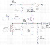
This is the circuit I want to simulate:
1725789673213.png


My AWR Design:
1725789630341.png


My Varactor Mode:
1725789732320.png


Transistor Model:
1725789761304.png


Spectrum Output:
1725789781187.png
 
It seems unusual to speak in terms of -300 dB. Is this an extremely weak output? For comparison I have a simulation using your parameters. I find that Falstad's animated interactive simulator supports a varactor model, furthermore the Circuits menu contains a similar circuit called VCO. Did you expect similar performance? Do you obtain similar performance?

VCO using varactor (1 GHz) per Edaboard Sep 8.png


The link below navigates to falstad.com/circuit, and runs my schematic on your computer. (The 1 ohm resistors ensure a sensible RC time constant so as to avoid convergence errors.) You may find a way to command a spectral display in scope settings.

tinyurl.com/2xp9kfjc
 
The oscillator has failed to start, either because it sits
on a quasi-stable point at DC OP and tolerance settings
"soak up" any lower-than-tol amplitude signal before it
can grow, or it's stuck for bad inputs / wiring / properties.

Easy to put a pulsed current source on one of the
nodes and give 'er a kick. What happens then, will tell
you what's preventing the desired activity.

You might look at the more direct results of whatever
analysis you ran, for more clues than the "processed"
spectrum plot offers (the waveform behind the numbers).
Be sure to give plenty more time than you think N cycles
should take to FFT, to allow for the "bloom time" to get
to periodic steady state.
 
In MWO when simulating an oscillator you need an OSCAPROBE, which initiate a large-signal oscillator simulation.
You can start first the simulation without the varicap circuit, only with a series LC resonator, and place later the varicap in the circuit.
 

Attachments

  • vco colpitts.jpg
    vco colpitts.jpg
    128.1 KB · Views: 17
Last edited:
Input Impedance of the Active Part does not have a Negative Resistance so this oscillator will not oscillate .
Either the circuit should be re-examined/Optimized OR another topology has to be chosen.

1725902908655.png

1725902925191.png
 
Last edited:
Of course it will not oscillate in your configuration because you forgot to place the series inductor part of the LC resonator.
The circuit oscillates fine. I tested with few simulators.
 
Of course it will not oscillate in your configuration because you forgot to place the series inductor part of the LC resonator.
The circuit oscillates fine. I tested with few simulators.
I didn't forget the Tank Circuit, I'm looking Input Impedance of the Active Part.
This part must have a Negative Real Part to sustain the oscillation.
 
Even for this, the series inductor part of the LC resonator should be placed in the circuit, otherwise you get wrong information..
 
If you change the Transistor as BFR193F ( my preferred oscillator transistor ) it works as I have already explained.
Negative resistance is present with a reasonable amplitude. Further optimization is always possible and should be done to improve the oscillator.
1726001283681.png

1726001299009.png

1726000797643.png

1726001002316.png

1726001082770.png
 

LaTeX Commands Quick-Menu:

Part and Inventory Search

Welcome to EDABoard.com

Sponsor

Back
Top