Continue to Site

Welcome to EDAboard.com

Welcome to our site! EDAboard.com is an international Electronics Discussion Forum focused on EDA software, circuits, schematics, books, theory, papers, asic, pld, 8051, DSP, Network, RF, Analog Design, PCB, Service Manuals... and a whole lot more! To participate you need to register. Registration is free. Click here to register now.

[SOLVED] Variable Low Frequency Generator

Status
Not open for further replies.

abuhafss

Full Member level 2
Full Member level 2
Joined
Aug 8, 2010
Messages
142
Helped
1
Reputation
2
Reaction score
0
Trophy points
1,296
Activity points
2,383
Hi

I want to build a variable low frequency generator.

Frequency range: 8Hz - 200Hz
Duty Cycle: 20% - 30%

I could not work out a suitable configuration for a 555 because the duty cycle conflicts when the frequency is increased.
Can anybody help me with this issue? Ah yes, 555 is not compulsory.....other devices like op-amp or transistors can be used.

Thanks
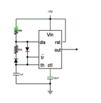
 

Attachments

  • 555 Timer.gif
    555 Timer.gif
    3.4 KB · Views: 91

There's a million of them. Do a google search for "square wave circuit". You can do this with an opamp, 3 resistors and a capacitor.
 

The basic method is to add a pot in series with your 82K, the wiper goes to the 39 k timing resistor and the other end goes to the diode and the DISS wire. Now when you twiddle the pot you are adding resistance to the discharge path and subtracting it from the charge path, or the other way around, i.e. it changes the mark/space ratio. Alter the cap and the 39K to set the actual speed.
Frank
 

Actually, I want to use only one POT to change the frequency such that the duty cycle should remain fixed.
 

Actually, I want to use only one POT to change the frequency such that the duty cycle should remain fixed.
Can't be easily achieved with a 555. A standard OP generator can do it, see post #2. Asymmetrical thresholds set the intended duty cycle, a single potentiometer the time comstant.
 

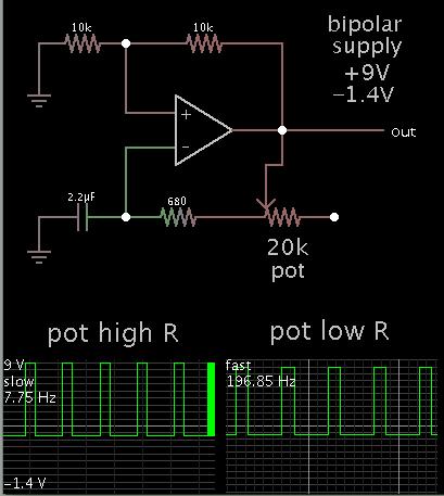
By feeding the op amp a lopsided supply, you can alter the duty cycle.

Simulation:

9504358200_1390046541.png


The left scope trace shows the lowest frequency (pot dialed to high resistance).

Then I dialed the pot to a low R, creating the high frequency (right).

By putting a diode at the output, you can obtain positive polarity only.

Or you might find a way to feed the op amp a single supply, and put a diode and resistor in a strategic spot in a feedback loop.
 
By feeding the op amp a lopsided supply, you can alter the duty cycle.
In the general case (single or symmetrical dual supply), a voltage divider would replace the 10k resistor to ground.
 
<BradtheRad>
Your configuration is suitable for my requirement.
Thanks a lot.

In the general case (single or symmetrical dual supply), a voltage divider would replace the 10k resistor to ground.
Yes, a 39k + 10k makes it perfect. Thank you, too.
 

Status
Not open for further replies.

Part and Inventory Search

Welcome to EDABoard.com

Sponsor

Back
Top