Continue to Site

Welcome to EDAboard.com

Welcome to our site! EDAboard.com is an international Electronics Discussion Forum focused on EDA software, circuits, schematics, books, theory, papers, asic, pld, 8051, DSP, Network, RF, Analog Design, PCB, Service Manuals... and a whole lot more! To participate you need to register. Registration is free. Click here to register now.

Using lm396/196 to convert 12v/18a to 7.5v/5.3a

Status
Not open for further replies.

deze4

Newbie level 4
Newbie level 4
Joined
Apr 12, 2009
Messages
5
Helped
0
Reputation
0
Reaction score
0
Trophy points
1,281
Activity points
1,330
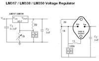
I want to convert a 12v/18A lead Acid battery to 7.5v/5.5A using the LM396. I am havin trouble understanding the datasheet; calculation of the two ext resistors that adjust Vout and the load current resistor that adjust Iout. how do i determine the value of the three resistors to be used or is there a better way to produce these outputs. the lm396 has a voltage range of 1.25v......30v/10A. i also dont understand where my negative battery terminal should be (Vin -ve).
Better still anyone who can give me a schematic so i can jst construct it i would be very grateful i'm jst a 100l engr student. someone pls help! LM396.JPGLM396A.JPG
 
Last edited:

If you set R! to a value (for example the 120 ohm shown in the datasheet) and then use the equation to calculate other resistor for the output voltage, the Iadj is very low (about 50uA) so it is ignored (set as 0) for practical calculations.
You can also use the LM317 calculator, the operation is the same

Alex

---------- Post added at 11:27 ---------- Previous post was at 11:25 ----------

Also note that you will have a lot of heat because you are using a linear regulator, the consumption on the regulator will be (12v-7.5v)*5.5A=24.75W so you need a big heatsink
 
  • Like
Reactions: deze4

    deze4

    Points: 2
    Helpful Answer Positive Rating
Hi,
According to National Semi datasheet LM196/396 is an adjustable voltage regulator from 1.25 v to 15 volts. You can use for higher output voltage but the difference between Vin-Vout should not exceed the specifications at the recommended Junction Temperature.
You can use R2 as 5K variable resistor and per my experience on LM196K regulator better you use a FORCED AIR cooling with reasonable Heat Sink.
 
  • Like
Reactions: deze4

    deze4

    Points: 2
    Helpful Answer Positive Rating
thnx Alex, found the calculator very useful. ok that solves one problem. thnx Raza, any suggestions what value of R3 should be, i think it sets Iout by limiting the ref current (Iref = 10A). can i use a small dc 12v motor fan for forced air cooling (which i connect directly to the battery). wow a large heat sink makes my circuit really bulky. is there any simpler circuit to arrive at 5.5A. perhaps by combination of a zener diode and darlington pair power transistors. and Alex please can u be more specific on the size of the heatsink. thanks alot
 

I can't tell you the heatsink size, you'll have to calculate it **broken link removed**

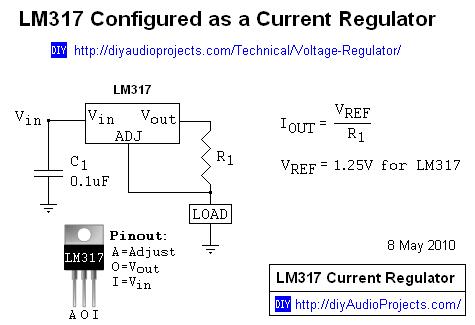
I don't think there is a point in using R3, all it does it supply a partial load current to reduce the power dissipation on the regulator but the amount of consumption that you reduce from the regulator will be consumed on the resistor so if you use the resistor to reduce 10w from the regulator then you will need a resistor >10W.

Alex
 

Hi,
R3 is pass resistor to load down the device heat by dividing the current. But in this case you have to have a minimum load always present until the power to the regulator is on. If you look page 9 of the datasheet it gives you the complete information and calculating R3. Here are few graphs for your reference for selecting heat sink without complex calculations:
Sink.jpgSink1.jpgSink2.jpg
Another advice is try using LM196 instead of LM396, as it has a better Junction temperature (200°C of Output Transistor).
Hope it may help a bit, any further query is welcomed.
Good Luck.
 

Attachments

  • LM196_396.pdf
    299.3 KB · Views: 128
  • Like
Reactions: deze4

    deze4

    Points: 2
    Helpful Answer Positive Rating
hi Raza, i did not use the LM396 again, i got the LM338 which has a nominal current value of 5A but peak value may exceeds 5a so it suits me just fine(5.3A). but thanks anyway your explanation of r3 will be very helpful in my future projects. My circuit works fine except for 1 thing the voltage drops by 0.01v evry 12 secs. i added capacitors at vin and vout to stop rippling; 1microfarad as stated in the data sheet. what could be causing this? also i read online that the lm338 can also be used as a current regulator. i intend to use a dc fan motor for the forced air cooling as u adviced
the highest amperage i could get was 850mA. can i merge a current stepdown cct into it so i can get another output of 7.5v/850mA. however the circuit description says nothing about the volt output where current has been regulated. can u help out on what to do. 7.5v will be 62.5% of max speed of the 12vdc fan. i think that should be okay cause its gonna be diretly over my circuit.

0_1314653714.jpg

Can this work? if nt please give me a gud alternative
 
Last edited:

Hi,
My circuit works fine except for 1 thing the voltage drops by 0.01v evry 12 secs. i added capacitors at vin and vout to stop rippling; 1microfarad as stated in the data sheet. what could be causing this?
Can you please post the image of your circuit enabling to look at the cause?
You not needed to add an other circuit, simply connect your 12Volts fan directly on the input (12 Volta) supply. It will work fine without problem.
Good Luck.
 

Image0150.jpgImage0151.jpgImage0153.jpgImage0145.jpg

this is what i have done so far, pls dont mind my heat sink i just used that for testing purposes, i've got a better one, i wuld use wen i'm fully finished. hope i gave enough angles for u to evaluate. the battery i'm using is 18A output will that not damage the fan(850ma)? Also i'm jst being curious; will the lm338 always deliver by default 5A, Irrespective of the current input from the dc source. for example using a 12v 2.5A battery as dc source to my circuit; do i still get 7.5v 5A? . I have a feeling its the fault of the variable resistor perhaps the resistance decreases as temp increases. what do u think? do i use a permanent linear resistor.
 
Last edited:

thanx raza and alex am all done found out the cause; it wasnt the variable resistor it was the 250 ohm resistor (R1), i used 1/4w and heat loss on it was quite high, increasing the temp which in turn increased resistance gradually and from the calculato as R1 increases vout decreases. i changed R1 to 1/2w and have included forced air cooling. it produce a steady 7.48v and 5.1A which is pretty gud.. do u hav an idea of the minimum dc voltage and current input to the lm338 because i would like to get a smaller portable battery. thnx
 

Status
Not open for further replies.

Similar threads

Part and Inventory Search

Welcome to EDABoard.com

Sponsor

Back
Top