Continue to Site

Welcome to EDAboard.com

Welcome to our site! EDAboard.com is an international Electronics Discussion Forum focused on EDA software, circuits, schematics, books, theory, papers, asic, pld, 8051, DSP, Network, RF, Analog Design, PCB, Service Manuals... and a whole lot more! To participate you need to register. Registration is free. Click here to register now.

Using LM324 and OP07 for controlling voltage

Status
Not open for further replies.

Hasan2017

Member level 4
Member level 4
Joined
Oct 23, 2017
Messages
76
Helped
0
Reputation
0
Reaction score
0
Trophy points
6
Activity points
831
Hello there,

This post might be a fun for learning, some of you might laugh to see it once!
Trying to control old TCA785, a phase control IC, https://images.100y.com.tw/pdf_file/TCA785P.pdf.

But before that, take a look my circuit in this attachment ….
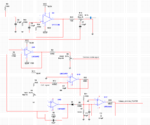
rectifier_v_control.PNG

1. Lets say 0-10 VDC signal in increments of 1 volt or a 0-20 mA signal in increments of 1 mA has given to inverting input of
U1D,pin 13, CVC signal.

2. At U1B, pin 5, reference voltage has applied, lets say 3-5 volt dc, its frequency dependent RC parallel feedback resistance contributing gain curve.


3. All op-amp has negative feedback.

4. Common mode signal is generated from external IC.


5. U1A looks like buffer amplifier.


6. U2 op07 looks like active low pass filter.

7. U1C and U1D positive pins are grounded!!

8. Not sure pot R6 and R16 are wrongly connected ?


Discuss and advice whatever you like to suggest for further development. i.e stable gain, linearity, impedance, noise!

Raise your hand where I am doing wrong

Calculation, signal analysis is necessary.
 

Hi,

First I'd like to say that the schematic is hard to read. Mostly just the placement makes it hard to read.
In future please try to combine the parts that belong together.
The signal flow should be from left to right. This means "input signals" should be at most left, not somewhere (hidden) in the middle of a schematic.

1) Like U1D circuit:
* it is a standard inverting Opamp circuit.
* R17 is the input resistor
* R12 and C5 are in parallel (confusing drawing!) and both are the feedback
The DC gain is: A = -R12/R17 = -100k/130 = 0.00077. That means a 10V input becomes 0.0077V at the output.
I don't think this is a useful signal range.

2)
"Reference" usually means a stable, clean signal. If you use 12V supply, then your reference is just that precise as the supply voltage. But a supply voltage usually neither is very stable nor very clean.
I recommend to use some stabilizing circuit (at least a zener), and use a capacitor to suppres higher frequency noise.
Use a useful resistor network to get the expected 3...5V range.

Rethink your resistor values. Resistors in the range of 100 Ohms cause 10mA with only 1V...thus you soon may reach the "output current" limit of your Opamps. Also consider the generated heat. 4V at 100 Ohms causes 40mA...but driven from a 12V supply it will cause about 1/2 Watt of overall heat (Opamp + resistor).
I recommend to use resistor values in 1k ...10k range...depending on curcuit.

C6/R14 don't act as a true filter, because the load resistor is missing. Indeed the circuit acts just as a buffer.

C7 doesn't make sense at all. There is no load resistor, thus the DC (output) voltage becomes unpredictable, nor one can calculate a cutoff frequency.

I assume U1C circuit is not correct. A resistor at the output ..fed to TCA..
...and then just a capacitive feedback...it makes the circuit to a pure integrator...expect the output voltage to clamp at either supply rail (unless there is a hidden DC feedback.

Klaus
 
  • Like
Reactions: Hasan2017

    V

    Points: 2
    Helpful Answer Positive Rating

    Hasan2017

    Points: 2
    Helpful Answer Positive Rating
Besides the mentioned points, what's the input signal to U2?


Stage U1C without DC feedback can make sense under circumstances if it's part of an overall feedback loop, e.g. PI controller. But hardly with the given low integrator time constants.
 

    V

    Points: 2
    Helpful Answer Positive Rating
U1A's NI input connects to a capacitor. There doesn't appear to be any DC bias.
 

First I'd like to say that the schematic is hard to read. Mostly just the placement makes it hard to read.In future please try to combine the parts that belong together.
The signal flow should be from left to right. This means "input signals" should be at most left, not somewhere (hidden) in the middle of a schematic.

Thank you very much Sir! Let me follow what you wanted to say. I have made it on PADS schematics, but for seek of simplicity and analysis, I have draw it in Multisim.


1) Like U1D circuit:
* it is a standard inverting Opamp circuit.
* R17 is the input resistor
* R12 and C5 are in parallel (confusing drawing!) and both are the feedback
The DC gain is: A = -R12/R17 = -100k/130 = 0.00077. That means a 10V input becomes 0.0077V at the output.
I don't think this is a useful signal range.

Nice feedback, lets say CVC signal is not 10V, we can start with 1 v first.

2) "Reference" usually means a stable, clean signal. If you use 12V supply, then your reference is just that precise as the supply voltage. But a supply voltage usually neither is very stable nor very clean.I recommend to use some stabilizing circuit (at least a zener), and use a capacitor to suppres higher frequency noise.Use a useful resistor network to get the expected 3...5V range.

The power supply I am using is well filtered, good SNR and more smooth, I think its stabilized as much as we can.


Rethink your resistor values. Resistors in the range of 100 Ohms cause 10mA with only 1V...thus you soon may reach the "output current" limit of your Opamps. Also consider the generated heat. 4V at 100 Ohms causes 40mA...but driven from a 12V supply it will cause about 1/2 Watt of overall heat (Opamp + resistor)
.


Yes, reasonable answer! I have find more suitable explanation here,https://electronics.stackexchange.c...sistor-values-for-inverting-amplifier-and-why, I think you might talking about this fact.


C6/R14 don't act as a true filter, because the load resistor is missing. Indeed the circuit acts just as a buffer.

This circuit is an application of rectifier controller.
I have forgot to add a Shunt (comes from rectifiers DC output)that should be add between U2 and U1A inputs, like common mode. Hence, C6/R14 filter could work. Sensing shunt is main fact here.
U2 out put has connected to U1A pin 2.

rc_v.PNG


C7 doesn't make sense at all. There is no load resistor, thus the DC (output) voltage becomes unpredictable, nor one can calculate a cutoff frequency.


An example please.


I assume U1C circuit is not correct. A resistor at the output ..fed to TCA..
...and then just a capacitive feedback...it makes the circuit to a pure integrator...expect the output voltage to clamp at either supply rail (unless there is a hidden DC feedback
.

Yes, also I am confused. Let me study it again.
 

First I'd like to say that the schematic is hard to read. Mostly just the placement makes it hard to read.In future please try to combine the parts that belong together.
The signal flow should be from left to right. This means "input signals" should be at most left, not somewhere (hidden) in the middle of a schematic.

Thank you very much Sir! Let me follow what you wanted to say. I have made it on PADS schematics, but for seek of simplicity and analysis, I have draw it in Multisim.


1) Like U1D circuit:
* it is a standard inverting Opamp circuit.
* R17 is the input resistor
* R12 and C5 are in parallel (confusing drawing!) and both are the feedback
The DC gain is: A = -R12/R17 = -100k/130 = 0.00077. That means a 10V input becomes 0.0077V at the output.
I don't think this is a useful signal range.

Nice feedback, lets say CVC signal is not 10V, we can start with 1 v first.

2) "Reference" usually means a stable, clean signal. If you use 12V supply, then your reference is just that precise as the supply voltage. But a supply voltage usually neither is very stable nor very clean.I recommend to use some stabilizing circuit (at least a zener), and use a capacitor to suppres higher frequency noise.Use a useful resistor network to get the expected 3...5V range.

The power supply I am using is well filtered, good SNR and more smooth, I think its stabilized as much as we can.


Rethink your resistor values. Resistors in the range of 100 Ohms cause 10mA with only 1V...thus you soon may reach the "output current" limit of your Opamps. Also consider the generated heat. 4V at 100 Ohms causes 40mA...but driven from a 12V supply it will cause about 1/2 Watt of overall heat (Opamp + resistor)
.


Yes, reasonable answer! I have find more suitable explanation here,https://electronics.stackexchange.c...sistor-values-for-inverting-amplifier-and-why, I think you might talking about this fact.


C6/R14 don't act as a true filter, because the load resistor is missing. Indeed the circuit acts just as a buffer.

This circuit is an application of rectifier controller.
I have forgot to add a Shunt (comes from rectifiers DC output)that should be add between U2 and U1A inputs, like common mode. Hence, C6/R14 filter could work. Sensing shunt is main fact here.
U2 out put has connected to U1A pin 2.


See the modified circuit.
rc_v.PNG


C7 doesn't make sense at all. There is no load resistor, thus the DC (output) voltage becomes unpredictable, nor one can calculate a cutoff frequency.


I assume U1C circuit is not correct. A resistor at the output ..fed to TCA..
...and then just a capacitive feedback...it makes the circuit to a pure integrator...expect the output voltage to clamp at either supply rail (unless there is a hidden DC feedback.
 

Status
Not open for further replies.

Similar threads

Part and Inventory Search

Welcome to EDABoard.com

Sponsor

Back
Top