Continue to Site

Welcome to EDAboard.com

Welcome to our site! EDAboard.com is an international Electronics Discussion Forum focused on EDA software, circuits, schematics, books, theory, papers, asic, pld, 8051, DSP, Network, RF, Analog Design, PCB, Service Manuals... and a whole lot more! To participate you need to register. Registration is free. Click here to register now.

Using a triac MAC97A with Arduino

Status
Not open for further replies.

boylesg

Advanced Member level 4
Joined
Jul 15, 2012
Messages
1,023
Helped
5
Reputation
10
Reaction score
6
Trophy points
1,318
Location
Epping, Victoria, Australia
Activity points
11,697
I have just played around with a MAC97A, just with 24VAC and a solenoid plus a 5VDC plug pack.
I triggered the gate through a 1N4007 and 56R resistor.
Eventually figured out that you need to connect DC GND to one of the triac terminals for it to trigger.

Is there any better way of protecting the DC circuit from the AC current than what I have done with the 1N4007?
 

You have enough familiarity in this forum to know that without providing accurate information the first thing that will happen here is others demand for details, as the schematic for example.
 

You have enough familiarity in this forum to know that without providing accurate information the first thing that will happen here is others demand for details, as the schematic for example.

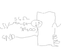
This is as good as the schematic is going to get. I don't have much in the way of motor skills when trying to draw and write with a mouse.

triac.png
 

A scribble done with a little more enthusiasm or less sloppiness would motivate someone to spend a time analyzing your problem instead of trying to decipher hieroglyphics. I`m quite sure you are plenty aware of the standard symbologies adopted for electronic devices.
 

Hi,

A pencil, a piece of paper and a photo...
A free schematic drawing software

Klaus

In your drawing I see "5V". But I assume thus "5V" is the supply voltage of an electronic device, but not the true voltage at this node.

If so, then this "5V" is useless, or even misleading informatikn.

Klaus
 

A scribble done with a little more enthusiasm or less sloppiness would motivate someone to spend a time analyzing your problem instead of trying to decipher hieroglyphics. I`m quite sure you are plenty aware of the standard symbologies adopted for electronic devices.

I don't know of any software that I can use to quickly knock up a schematic, in a generic format, that I can quickly and conveniently post in here.

I could do it with Multisim but I am doubting many others will have that software installed and able to open the files it generates.

Surely you could find it in your heart to overlook my clumsy scribble in Paint.net for such a trivial circuit?????

- - - Updated - - -

Hi,

A pencil, a piece of paper and a photo...
A free schematic drawing software

Klaus

In your drawing I see "5V". But I assume thus "5V" is the supply voltage of an electronic device, but not the true voltage at this node.

If so, then this "5V" is useless, or even misleading informatikn.

Klaus

If you knew how slow and painful it is to get photos off my phone or scanner you would understand why I went for the quick and nasty option of paint.net.
I wouldn't have done this if it was a more complex circuit. But this one is so brainlessly trivial that I thought people would be prepared to overlook it.

- - - Updated - - -

Hi,

In your drawing I see "5V". But I assume thus "5V" is the supply voltage of an electronic device, but not the true voltage at this node.

If so, then this "5V" is useless, or even misleading informatikn.

Klaus

5V as in the triac gate is triggered by 5V from an Arduino digital pin.

Or in the case of my breadboard experiment, 5V from a phone re-charger plug pack in lieu of an Arduino digital pin.
The 56R resistor combined with the 1N4007 seems to trigger my solendoid valve adequately.
A 820R resistor seems to cause the solenoid to 'run rough'. I presume because the triac is not fully turned on and it is chopping up the AC current to lower frequency chunks of the sine wave.

All I want to know is if there is any point in having that 1N4007.

Or is their a better way to protect my DC circuit and Arduino from 24VAC if that triac was to fail?

Up until now I have used relays where the two circuits are totally isolated from one another.

It is the first time I have used a triac though.
 

Hi,

5V as in the triac gate is triggered by 5V from an Arduino digital pin.
The Arduino is supplied with 5V, this doesn't mean the pin output voltage is 5V, too.
It may be close to 5V with zero current...
But the pin voltage will drop with current. And your circuit draws some current.

If you knew how slow and painful it is to get photos off my phone or scanner
What's exactly the problem? It should be a standard and easy function for a phone as well as scanner to create and digital picture files.

Klaus
 

Is there any better way of protecting the DC circuit from the AC current than what I have done with the 1N4007?

How about using an opto-coupler? Safety first (I am talking about the poor arduino) even if you are using 24AC.
 

How about using an opto-coupler? Safety first (I am talking about the poor arduino) even if you are using 24AC.

I did end up discovering optocoupler triacs. But I have a heap of TO-92 triacs. Is there no reliable way of protecting the DC part of the circuit from a failed triac? Diodes, zenner diodes,...?

- - - Updated - - -

I am all eyes if some one has a suggestion as to a quick and simple software package that lets you create schematics, in jpg format, by dragging and dropping circuit symbols as opposed to specific components.
 

Hi,

there are a lot of free schematic drawing tools. You may find discussions here in this forum.
Many of them can directly generate .jpg files.

But you also can use the OS "screenshot" function to generate a .jpg.

Klaus
 

The simplest drawing tool is probably FidoCadJ which is written in Java and runs on most platforms. In my opinion it doesn't come close to the Kicad/Eagle/Protel type of programs for functionality but it is small, free and very easy to use.

Looking at the original problem, I can't see how anything but an isolated connection can be safe here. Even at 24V, if the ground side isn't good it will just push a negative voltage into the Arduino and kill it instantly. I'm not sure the voltage/current capability of the port is sufficient either and even if it was, the triac couldn't possibly fire in all quadrants.

Brian.

Oh! Someone at some point was telling me I ought to use triacs instead of relays for my irrigation controller. But it looks as though it is simpler to just stick with relays.
 

Hi,
Is there no reliable way of protecting the DC part of the circuit from a failed triac?
What is reliable?
I recommend to read through the datasheets and keep within their specifications, then it should be reliable.
If you don´t need isolation, then I see no reasn why you should use optocouplers.

My recommendation: Don´t protect your DC part from failing triac, but protect the triac from fail.

*****
Your circuit with diode for protection:
It only can protect against one error: the gate goes high positive voltage caused by a damaged triac... Then the diode will protect the driving circuit.
But when the gate goes high positive voltage, then I expect it to go high negative voltage, too...now the diode doesn´t protect anymore.
****

From your description we can not know whether a relay or a triac is suitable.

Btw: What if the relay fails?

Klaus
 

Hi,

What is reliable?
I recommend to read through the datasheets and keep within their specifications, then it should be reliable.
If you don´t need isolation, then I see no reasn why you should use optocouplers.

My recommendation: Don´t protect your DC part from failing triac, but protect the triac from fail.

*****
Your circuit with diode for protection:
It only can protect against one error: the gate goes high positive voltage caused by a damaged triac... Then the diode will protect the driving circuit.
But when the gate goes high positive voltage, then I expect it to go high negative voltage, too...now the diode doesn´t protect anymore.
****

From your description we can not know whether a relay or a triac is suitable.

Btw: What if the relay fails?

Klaus

I am only puting 24VAC through the relay.

And as far as I am aware, the DC coil and the AC contacts are sufficiently isolated for there to be no consequences if the AC contacts short circuit or something.
Am I wrong about that assumption?

The application is for using and Arduino to switch 24VAC through a solenoid valve.

What is your suggestion for protecting the triac from fail? Fuse perhaps?
I have never used triacs before with my Arduinos so I am really only making educated guesses about protection at this point.

- - - Updated - - -

The fact that I had to connect DC GND directly to the AC circuit to get the triac to trigger sort of alarms me a bit.

Are there any undesirable side effects of this......like AC ringing leaking into the DC circuit and upsetting the Arduino (puting aside the issue of whether or not the Arduino has sufficient current to directly trigger the triac).
 

Connecting the two circuits together (AC and DC) is not impossible but you have to be extremely careful with current paths and consider what happens if for example the AC is present but the DC fails. The diode will offer no protection, it would just act as a negative voltage rectifier and feed the DC to the Arduino pin in the wrong polarity.

By FAR the best solution here is to use an opto-isolator such as a MOC304x to fire the triac. It gives excellent voltage isolation, can be driven directly from the Arduino (via a single resistor to limit LED current) and it will let the triac conduct over the whole AC cycle instead of only half of it. They are very reliable, small, inexpensive and cost less than a relay!

Brian.

Thankyou for the suggestion about fidocad. I tried it and it is perfect - quick and simple.

What is your opinion of these optocoupled triacs Brian?

https://www.ebay.com.au/itm/10PCS-MOC3023-OPTOCOUPLER-TRIAC-OUT-6-DIP/323030869254?hash=item4b3623e506:rk:1:pf:0

 
Last edited:

Hi,

And as far as I am aware, the DC coil and the AC contacts are sufficiently isolated for there to be no consequences if the AC contacts short circuit or something.
Am I wrong about that assumption?
"sufficiently isolated": We don´t know which relay you use, thus we don´t know if it is sufficiently isolated.

You talk about "failing triac"
* if the triac doesn´t fail the DC part will have no problems. (the same is with the relay)
so let´s talk about the "fail" situation.
* if the triac fails your DC part may get damaged. The same is with the relay. If the isolation barrier within the relay fails, then your DC part may get damaged.

Now you may say you don´t expect the relay to fail.
--> correct, if you operate the realy within it´s specifications. But again: the same is true for a triac: It won´t fail as long as you operate it within it´s specifications.

What is your suggestion for protecting the triac from fail? Fuse perhaps?
Why does an electronic part fail:
* overvoltage --> use an overvoltage protection
* overcurrent --> use an overcurrent protection (maybe a fuse)
* overtemperature --> keep the temperature within specifications.
The same applies to the relay.

I have some decades of experience with electronic circuits and also with relays.
I´ve seen triacs to fail and I´ve seen relays to fail. Most of them (who faild) were not operated properly.
Relay contact may
* stick together, caused by overcurrent, mechanical mistreatment (ultrasonic),
* isolation problems due to overvoltage humidity, water,
* false open or high contact resistance by too low switching current, or voltage... dirt, humidity...
* coil breakdown..
similar to triacs..

I personally like th tricas because they have no mechanical moving parts.

Klaus

added: What about "solid state relays"? They come with AC, DC switching capabilities, zero cross switching or direct switching, with and without protection.
 

What is your opinion of these optocoupled triacs Brian?

If you have lots of triacs already in pocket, you can just get a set of general purpose optocouplers. And they can be used in other places too. Because you are trying these circuits, it is good to be careful.
 

If you have lots of triacs already in pocket, you can just get a set of general purpose optocouplers. And they can be used in other places too. Because you are trying these circuits, it is good to be careful.

I have already designed a PCB for my irrigation controller and those 6 pin PDIPs still fit in nicely.

It will be more difficult to fit in a separate dc optocouplers and triacs.

It doesn't matter all that much as they didn't cost that much from ebay china and I can always use them for another project in combination with a dc optocoupler.

I'll put it down to inexperience with triacs - bought them before I understood fully how to use them.
 

I'll put it down to inexperience with triacs - bought them before I understood fully how to use them.

It is part of the learning process; I call learning from experience is "google learning"- like a neural network learns from a trial data set. Such trainings are rather incomplete and for a good result need tons of training data...

But if you read a lot and are able to understand the technical jargon- unfortunately jargon is a great barrier- you will learn faster because you are now learning from others' experience. But the technicalities can become messy rather fast.

A good engineer needs to be practical; you will need to be good in both theory and practice. Else you will be only a simple technician: both have their respective positions but they remain different.

I often call understanding a kind of enlightenment...
 

Status
Not open for further replies.

Part and Inventory Search

Welcome to EDABoard.com

Sponsor

Back
Top