Continue to Site

Welcome to EDAboard.com

Welcome to our site! EDAboard.com is an international Electronics Discussion Forum focused on EDA software, circuits, schematics, books, theory, papers, asic, pld, 8051, DSP, Network, RF, Analog Design, PCB, Service Manuals... and a whole lot more! To participate you need to register. Registration is free. Click here to register now.

Use of positive feedback in opamps?

Status
Not open for further replies.

snishanth512

Full Member level 3
Full Member level 3
Joined
Nov 12, 2012
Messages
159
Helped
13
Reputation
26
Reaction score
13
Trophy points
1,308
Location
India
Activity points
2,135
Why are we using positive feedback for low-pass and high-pass filter?
 

Why are we using positive feedback for low-pass and high-pass filter?
Do we? Can you please give an example of the circuit topologies you are talking about.
 

Could you please post an example? Most of the filters use feedback on the neg input of the op amp. The only exception could be the Sallen-key which has a capacitor as a feedback to the pos . But it has negative feedback in DC.
If you are concerned with stability, the phase margin and the gain margin of the complete circuit should be studied.
 

Why are we using positive feedback for low-pass and high-pass filter?
Do we? Can you please give an example of the circuit topologies you are talking about.
Hi
I think the the original poster's meaning , is a sine wave oscillator !
The positive feedback , will be required to tendency awards to the oscillation ! and that LPF will select the frequency of oscillations .
Best Wishes
Goldsmith
 

Why are we using positive feedback for low-pass and high-pass filter?
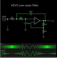
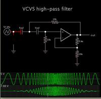
There is an animated simulator which portrays operation of this topology.

VCVS, high-pass and low-pass.


By clicking the link below you can watch the simulation, and see current flow getting weaker or stronger in the positive feedback (upper) loop.

The links below will open the falstad.com website, load the schematic, and run it on your computer. (Click Allow to load the Java applet.)

High pass:

https://tinyurl.com/cjphwjh

Low pass:

https://tinyurl.com/bfng97s

The circuits are included in the menu of circuits that come with the app.
 
I don't see any indication that the original question is referring to oscillators.

Positive feedback in general involves of course the possibility of continuous oscillations. I agree to albert22, that the post is most likely talking about Sallen-Key topology.

The usual implementation uses an unity gain buffer and thus restricts loop gain to unity as well. The circuit might oscillate only by the effect of additional OP poles, but not with ideal components. There's howvever a modification of Sallen-Key with > unity gain, which can easily oscillate.

Referring to common filter prototypes (bessel, butterworth, chebyshev), Sallen-Key positive feedback topology can achieves the same results as negative MFB (multiple feedback). There are minor differences in sensitivity to component tolerances, but both topologies are used side by side in electronic design.
 

Why are we using positive feedback for low-pass and high-pass filter?

Coming back to the original question: WHY...?

The answer is as follows:
*Passive RC filters allow negative-real poles only (very bad selection properties)
*Thus we are using either passive RLC filters, which enable conjugate-complex pole pairs by exploiting the resonance effect (and improved selection properties), or
*We use active RC filters, which also cause conjugate complex poles if positive signal feedback is applied (typical example: Sallen-Key structures, however with negative dc feedback)

Comment
: However, all other active filter topologies also apply positive signal feedback and negative dc feedback (MFB, Integrator filter,...) insofar as the signal feedback network causes a corresponding phase shift, which in conjunction with the inverting input terminal of the opamp acts as positive feedback.

In summary: To construct active RC filters with good selectivity (Butterworth, Chebyshev,...) we need complex pole pairs, which can be realized with positive signal feedback only (in addition, a stable bias point requires negative dc feedback) .

Supplement: To complete the picture it should be added that there are also "negative-gain Sallen-Key structures" (with much larger negative fixed gain values than the classical pos. gain S+K topologies). However, here the same applies: The feedback network (connected to the inv. input terminal) introduces phase excursions, which turn the negative into a positive signal feedback.
This is a good example to verify that "positive feedback" not necessarily means: Feedback network is connected to the non-inv. input terminal.
In turn, there are cases where negative feedback is connected to the non-inv. terminal (if phase inversion takes place within the feedback path). Example: Actively phase-compensated opamp circuits.
 
Last edited:
With respect to my last post perhaps the question arises: How is negative/positive feedback defined?
Requires negative feedback a phase inversion?
Is the phase=0 deg for positive feedback?

The general definition is based on the classical feedback formula

H(s)=N(s)/D(s) with D(s)=[1-T(s)].
With T(s)>>loop gain.

Simple case:

*T(s) negative >> T(s)=-|T(s)| >> negative feedback
*T(s) positive >> positive feedback.

General definition:


|1-T(s)|>1 means: negative feedback
|1-T(s)|<1 means: positive feedback

In the Nyquist diagram for the loop gain T(s) the transition from negative to positive feedback can be found at the point where the diagram crosses the unit circle around the "critical point +1"

- - - Updated - - -

For demonstration purposes I enclose a graphical representation of the above definitions.
Example: Opamp (Ao=100 dB) with two corner frequencies (16 Hz, 1.6 MHz) in unity gain configuration.
Note that for frequencies higher than 1 MHz the negative feedback turns into positive feedback (without stability problems because the gain magnitude is already below unity).
This (stable) positive feedback causes a certain amount of gain peaking around 1 MHz.

Legend: The sensitivity function S is defined as S=1/|1-T(s)|

Hint: In the picture (attachement) : Loop gain H(s)=T(s)
 

Attachments

  • pos_neg_feedback.pdf
    54.5 KB · Views: 181
Last edited:
well positive feedback is when a part of the output is given back to the input so that the output increases more. this is done to produce oscillations. and negative feedback is when a part of the output is given back to the inputs so that the output decreases more. this is done to stabilize the gain of an amplifier.

positive feedback is also known as regenerative feedback and negative feedback is also known as degenerative feedback.

a great example of the usefullness of negative feedback is the opamp. before the days of the opamp, amplifiers were built to have a large gain. but every time the gain got instable because of temperature effects. the idea in the opamp was to produce an amplifier that had lots of gain and with using negative feedback the gain could be brought down. it was seen as the perpetual motoin machine. with producing a large gain and then using negative feedback the amplifier becomes independent of the characteristics of the opamp. it just depends on the external components which are resistors. so now the gain is not dependent on temperature.

i hope that helps
 

Status
Not open for further replies.

Similar threads

Part and Inventory Search

Welcome to EDABoard.com

Sponsor

Back
Top