Continue to Site

Welcome to EDAboard.com

Welcome to our site! EDAboard.com is an international Electronics Discussion Forum focused on EDA software, circuits, schematics, books, theory, papers, asic, pld, 8051, DSP, Network, RF, Analog Design, PCB, Service Manuals... and a whole lot more! To participate you need to register. Registration is free. Click here to register now.

Use a BT136 (TRIAC) and a LM555 to autoswitch AC

Status
Not open for further replies.

jumpman

Newbie level 6
Newbie level 6
Joined
Aug 26, 2011
Messages
13
Helped
2
Reputation
4
Reaction score
2
Trophy points
1,283
Activity points
1,370
Good afternoon.

I am trying to use a TRIAC to turn on and off the mains connection to a load. This load is directly connected to the mains (without a transformer) because it is a Cockroft Walton Ioniser (with capacitors and diodes). I'd like to use the TRIAC with this configuration: where the lamp is replaced by my load (ioniser).
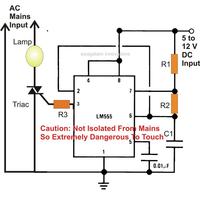
Is it possible?

circuit is very dangerous ... you should use a optocoupler MOC 3021 from output 555 to the input TRIAC
 

    V

    Points: 2
    Helpful Answer Positive Rating
And there's no need for an additional transistor:
 

Attachments

  • NE555 mainsSwitch.png
    NE555 mainsSwitch.png
    16.2 KB · Views: 182

Hi because at the original post the designer used 555 , it's out put current will be enough to drive an opto triac simply , and i don't think the transistor after that required .
Best Wishes
Goldsmith
 
Hi because at the original post the designer used 555 , it's out put current will be enough to drive an opto triac simply , and i don't think the transistor after that required .
Best Wishes
Goldsmith

Thank you =). The thing is that i can't see the digital signal after the optocoupler (the square signal only appears between the 555 and the opto). I'm testing it with the mains terminals open. How can i test this control part without connecting the mains?
 

I'm confused , about what you need exactly , can you tell me a bit more explanation , please ? and a question : why you can't use square wave to drive your triac ?
Best Wishes
Goldsmith
 

Circuit.JPG This is the circuit with control. The objective is to automatically turn on and off the main circuit. The 555 generates a 2 Hz sq signal and the optocoupler should send it to the TRIAC gate pin. This would turn on and of my ioniser circuit.
 
Last edited:

Well , you didn't tell , why you can't use square wave for your triac ?
is the input of triac sine wave ?
And i can't realize that what is your problem here ??!!
Respect
Goldsmith
 

Hello goldsmith. I never said i can't use square wave to control the TRIAC. I can. I just said that the control is not working because the opto doens't show any output....
 

Hi jumpman
I think your opto coupler burned .
Because it's input is 12 volts with a 220 ohms resistor . i think 220 ohms i s very low for that see it's datasheet at LED specifications section .
BTW : when i saw it's datasheet , it designed for 220 volts AC , we have a safety ratio about *2 ! you should use
MOC3021 (itdesigned fo 400volts AC) not MOC3020 .
Best Wishes
Goldsmith
 
The MOC3020 thru MOC3023 series use a 400V phototriac output so any type can be used for 240Ac applications. And as goldsmith already mentioned, for a standard operation we must limit the optocoupler input current at 15mA-20mA, see the datasheet:
**broken link removed**
In this particular application need to increase the resistor value up to 560- 620 ohms.
I think the main problem is related to the load. In order to determine whether there is anything wrong to the circuit connections we need to test first using an incandescent light bulb (40W-60W/230V). So remove the ioniser circuit, connect a light bulb instead and do the test. :cool:
 
Hi jumpman
I think your opto coupler burned .
Because it's input is 12 volts with a 220 ohms resistor . i think 220 ohms i s very low for that see it's datasheet at LED specifications section .
BTW : when i saw it's datasheet , it designed for 220 volts AC , we have a safety ratio about *2 ! you should use
MOC3021 (itdesigned fo 400volts AC) not MOC3020 .
Best Wishes
Goldsmith

Ok now i understand. I wasn't looking at the specs cause i saw this opto used in many application. Ill be more carefull. I have 2 more units of the MOC3020, but none of the MOC3021.

---------- Post added at 09:46 ---------- Previous post was at 09:44 ----------

The MOC3020 thru MOC3023 series use a 400V phototriac output so any type can be used for 240Ac applications. And as goldsmith already mentioned, for a standard operation we must limit the optocoupler input current at 15mA-20mA, see the datasheet:
**broken link removed**
In this particular application need to increase the resistor value up to 560- 620 ohms.
I think the main problem is related to the load. In order to determine whether there is anything wrong to the circuit connections we need to test first using an incandescent light bulb (40W-60W/230V). So remove the ioniser circuit, connect a light bulb instead and do the test. :cool:

Thank you for your reply! Ill try to find an incandescent light bulb to test the MOC3020 with a higher value resistance. I don't have the MOC3021.
 

@goldsmith
You can see in the datasheet, all the 220VAC applications use the complete MOC3020-MOC3023 series, the only difference related to the input triggering current, lower input current for the MOC3023 and higher for the MOC3020.
 

Hi again
Yes , i saw it's examples , but i think MOC3021 has more safety. isn't it ?
Best Regards
Goldsmith
 

No, that’s more efficient, measured through its current transfer ratio (CTR), which is the relationship between the current change on the output side of the barrier and the current change on the input side of the barrier, but regarding the output voltage the MOC 3020-3023 series was designed to withstand peaks of 400Vcc.
 

Status
Not open for further replies.

Similar threads

Part and Inventory Search

Welcome to EDABoard.com

Sponsor

Back
Top