J
Javid.zare.s
Guest

Follow along with the video below to see how to install our site as a web app on your home screen.
Note: This feature may not be available in some browsers.


Thks man , i tested resistance of them , one of them showed around 1.5kohm (not a diode)Hi,
They could be Zener diodes, TVS, maybe resistors or even capacitors.
Maybe reading these could be of help:
**broken link removed**
I searched for this: usb pinout d+ and d- with diodes. These are the results.


Hi,
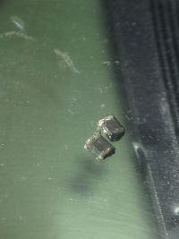
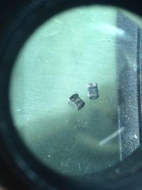
Personally, I would not replace the two burnt parts with random components, it could harm other parts of the mainboard or just do nothing of use. One approach would be to desolder those two parts from the board and then do continuity and resistance tests. Another, more time-consuming, would be to try to locate the board's reference number/name, then see if you can find a schematic online somewhere, or a link to a PC repair web where it is discussed, and see if any concrete information comes up about those two parts before doing anything regrettable.
Sometimes measuring resistance on a pcb can be misleading, so perhaps it's best be a little wary of them being 0 ohms and 1K5, even if those turn out to be the real values.
I'd search around a bit for the mainboard part number. Also, it looks unlikely 'though, maybe cleaning the top of those components with a cotton wool bud (and if necessary e.g. 96% alcohol) might help to show what's left of any markings - best to get them off the board first if possible.
Not sure what else I could suggest.
Any idea as to what caused this to happen each time? Is the board very old? Did you connect something with a different wiring where data and power, or power and ground were reversed? It would be interesting to know what causes that to happen.
The burnt out component next to the other zero ohm resistors is probably another zero ohm resistor, these are often used as fuses, the other burnt out component is probably a fuse. Try putting a link across them you have little to lose.


Hi,
Have you looked through pictures of various SMD diodes? I can't see from the photo if the two burnt components have pins at the bottom, but from the top they look quite a lot like diodes (if the grey strip was grey before they got burnt and the other end didn't have the same marking). Which doesn't mean they are not, as suggested, 0 Ohm resistors. Out of curiosity - I don't have any burnt resistors to hand - I just measured a 1N4007 diode on the DMM ohmmeter setting, and it either read O.L. or with the connection reversed the value rose slowly; I also tried with a 10nF capacitor (in the unlikely event of yours being polymer capactors) but that just read O.L. so I do not know why that happens when you measure them.
If you measured the resistance with them still soldered to the board you can expect odd things to happen with the readings - if you can, which may be too difficult for whatever reasons, you should remove them (they are burnt, after all) and then measure them.
Another thing with mainboards, like when cleaning the fan: disconnect mains lead (and remove battery if a laptop), then press the on button a few times to discharge the capacitors before doing anything.
I don't know what to say, as I can appreciate it not being appealing just trying random things out. If you can't get hold of a description of the mainboard from its part number, ask around on PC repair forums. It's common sense.


You must remember that the highest voltage on a USB port is only 5V to have enough power to burn out those devices would require them to be of low resistance or a diode. For example a 1.5K resistor cannot burn out unless you fed a high voltage back into the USB port. For a resistor to burn out it would have to be less than 30 ohms or so. I would try and replace the burnt out components one at a time with fuse wire rated at a few hundred mA and see what happens.


Both of these components are just ferrite beads. As you can see they are located on the power traces. Usually, these are 300 to 600 Ohms with 1A current rating.


300 ohms is an impedance of a ferrite bead usually specified at 100MHz. Its DC resistance will be much lower, somewhere around 0.3Ohm.
Hope this helps
