gres
Full Member level 4

UNUSUAL BULB = RGB

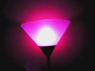
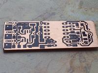
I wanted to design special project - to stuff electronics to normal bulb, so "she" can do something amazing. Only think that sprang to my mind ( except bomb with thermometer) was bulb that can smoothly change colures. To build that project you need converter 230V/5V-500mA, LED diodes - SuperFluxRGB, driver based on ATTiny13 microcontroller in SOIC cover - program based on Bascom, all fit to 2cm x 4,5 cm plate.
Converter is a simple charger with USB output, that can give 5V on output while 500mA load. I bought cheapest charger. It has only two transistors, works with 5,5V / 400mA. When 500mA voltage fall down to 4,98V.
Driver has three operating modes:
- smoothly change colures
- one colour , the same as on first mode
- white colour
Driver remember last operating mode, so even while sudden stop, it always start at effect that was last display. How to change operating modes, if all device is closed in glass bulb? Simple, by cutting voltage for a while, then bulb change mode. Microcontroller is 1N1418 diode - powered and memory backup capacitor 220uF, so it can work about 2 seconds after power cut down. At one of the pines, is simple chipset to detect power cut. It is diode (again 1N1418) and 1K resistor) - works very fast.
Which resistor choose it's up to you, depend on what kind and how many diodes we have. Resistors match that not overload diodes or converter. I used 5 diodes, three with different colours each structure, voltage for each is 20mA. So when we want white colour, all diodes must work, so we have maximum 300mA.
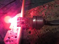
I grind off diodes by sandpaper because frosted diodes better split ray light.


Full description at :
https://www.elektroda.pl/rtvforum/topic1494387.html

I wanted to design special project - to stuff electronics to normal bulb, so "she" can do something amazing. Only think that sprang to my mind ( except bomb with thermometer) was bulb that can smoothly change colures. To build that project you need converter 230V/5V-500mA, LED diodes - SuperFluxRGB, driver based on ATTiny13 microcontroller in SOIC cover - program based on Bascom, all fit to 2cm x 4,5 cm plate.
Converter is a simple charger with USB output, that can give 5V on output while 500mA load. I bought cheapest charger. It has only two transistors, works with 5,5V / 400mA. When 500mA voltage fall down to 4,98V.
Driver has three operating modes:
- smoothly change colures
- one colour , the same as on first mode
- white colour
Driver remember last operating mode, so even while sudden stop, it always start at effect that was last display. How to change operating modes, if all device is closed in glass bulb? Simple, by cutting voltage for a while, then bulb change mode. Microcontroller is 1N1418 diode - powered and memory backup capacitor 220uF, so it can work about 2 seconds after power cut down. At one of the pines, is simple chipset to detect power cut. It is diode (again 1N1418) and 1K resistor) - works very fast.
Which resistor choose it's up to you, depend on what kind and how many diodes we have. Resistors match that not overload diodes or converter. I used 5 diodes, three with different colours each structure, voltage for each is 20mA. So when we want white colour, all diodes must work, so we have maximum 300mA.
I grind off diodes by sandpaper because frosted diodes better split ray light.


Full description at :
https://www.elektroda.pl/rtvforum/topic1494387.html