Continue to Site

Welcome to EDAboard.com

Welcome to our site! EDAboard.com is an international Electronics Discussion Forum focused on EDA software, circuits, schematics, books, theory, papers, asic, pld, 8051, DSP, Network, RF, Analog Design, PCB, Service Manuals... and a whole lot more! To participate you need to register. Registration is free. Click here to register now.

Understanding of Switched Capacitor Amplifier

Status
Not open for further replies.

taik

Member level 3
Member level 3
Joined
Oct 22, 2007
Messages
58
Helped
1
Reputation
2
Reaction score
0
Trophy points
1,286
Visit site
Activity points
1,604
Hi all,

I am trying out a simple SCA setup in simulation to understand the principles of SC.

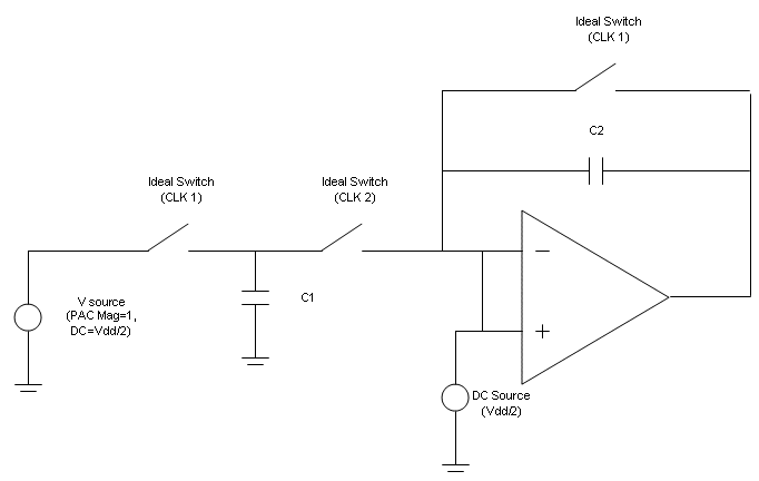
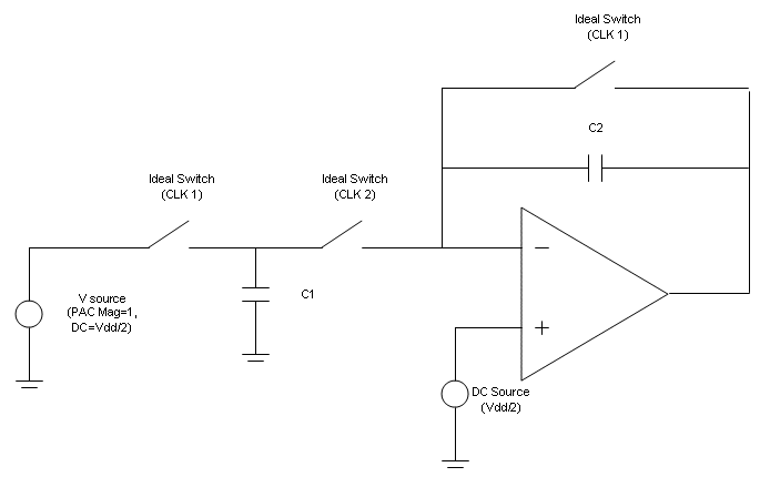
Below shows 2 pictures of the testbenches I have tried. Which should be the correct one?

I have tried both but unable to get a gain of C1/C2 after running a PSS and PAC analysis in Spectre. I got -50dB gain from PAC plot when my C1/C2=32.

May I know what I should take note of here?

Gain of op-amp is abt 50dB while ideal switches are used from analogLib for the time being.

Thank you.

DC Bias at 1 Input
sc_setup1.gif


DC Bias at Both Inputs
sc_setup2.gif


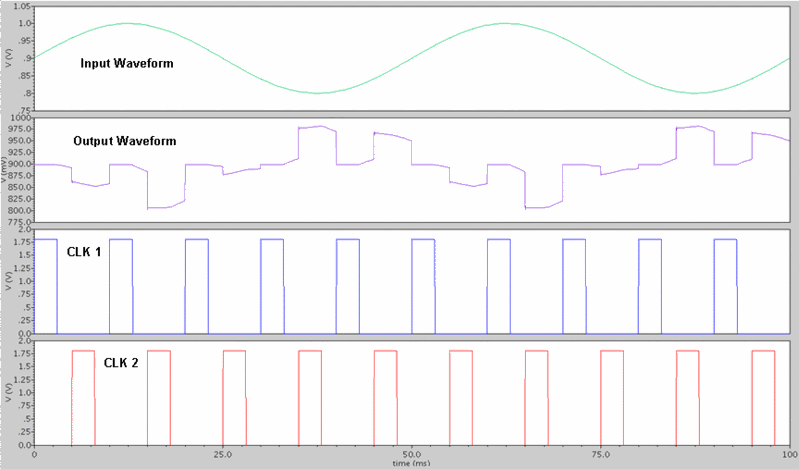
Waveform from Circuit 1 for C1/C2=1
wave.gif
 

hi taik,

the first plot is right.

you should ensure that CLK1 and CLK2 are the non-overlapped clocks firstly.

just simulate it using transient analysis and check the operating point of opamp and the output.
 

i have used non-overlapping clocks for CLK1 and CLK2
 

I was wondering if the output voltage is right because C1/C2=1. The output voltage is supposed to be 1V when Vin is 0.8 and it is @ 0.8V when Vin is 1V. It turns out this opamp can not go up. That is my another question.
 

hi yschuang,

it can still go higher than 0.8V...

but in the first place, is the shape of the output shape correct?
 

Delta Vin=0.1v and it is an inverting amplifier. Therefore, delta Vout=- delta Vin.
Vout is supposed to be 0.9+delta(Vout), which is 0.9+0.1 when delta(Vin) goes from 0.9 to 0.8. I noticed that Vout goes higher roughly @ 0.975 when Vin is 0.8V.
I will implement an ideal opamp, which is EXXX in Hspice, to compare the result.
Or add an ideal opamp after your own amplifier to get the opposite phase. Doing that you can compare the result with your input.
 

Hi taik, your clock frequency is only (roughly spoken) 5 times higher than the signal frequency. Is this configuration just a test or the final design ? As a rule of thumb, in practice the frequency ratio should be at least 50 !
 

Status
Not open for further replies.

Part and Inventory Search

Welcome to EDABoard.com

Sponsor

Back
Top