LeanSol345
Junior Member level 2

Hi, I'm using Rasp-Pico to read registers from ADE7758. I want to read registers that are Non-Zero by default e.g. OPMODE (address:0x13; def-value:4) and I don't think external circuit for Voltage or Current measurements will matter while reading just these registers (default non-zero). SPI communication is initialized by phase=1; polarity=0 and the OUTPUT is 0 (ZERO).
I think there could be an issue while settling SPI, polarity or phase (but I'm unable to understand it). I've tried different polarity and phase bits in SPI but no use.
Here is the CODE, I'm writing:
read_command is to take the register in 8-bit as 0x7F will make communications register = 0111 1111, so the MSB will define read operation (Low logic) as per ADE7758 datasheet.
ChipSelect is initially zero to write register address to ADE7758 in order to read it. (As per my understanding, this is how it should be done.)
[ OPMODE = 0x13
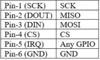
spi = SPI(0, baudrate=5000000, phase=1, polarity=0, sck=Pin(2), mosi=Pin(3), miso=Pin(4))
cs = Pin(5, Pin.OUT)
def read_register(address):
try:
read_command = 0x7F & address
cs.value(0)
spi.write(bytearray([read_command]))
time.sleep_ms(1)
data = spi.read(1)
cs.value(1)
return data[0]
except Exception as e:
print("Failed to read from SPI: ", e)
return None
def main():
MODE_VAL = read_register(OPMODE)
print("Register Value is: ", MODE_VAL)
while True:
main()
time.sleep(2)
]
I think there could be an issue while settling SPI, polarity or phase (but I'm unable to understand it). I've tried different polarity and phase bits in SPI but no use.
Here is the CODE, I'm writing:
read_command is to take the register in 8-bit as 0x7F will make communications register = 0111 1111, so the MSB will define read operation (Low logic) as per ADE7758 datasheet.
ChipSelect is initially zero to write register address to ADE7758 in order to read it. (As per my understanding, this is how it should be done.)
[ OPMODE = 0x13
spi = SPI(0, baudrate=5000000, phase=1, polarity=0, sck=Pin(2), mosi=Pin(3), miso=Pin(4))
cs = Pin(5, Pin.OUT)
def read_register(address):
try:
read_command = 0x7F & address
cs.value(0)
spi.write(bytearray([read_command]))
time.sleep_ms(1)
data = spi.read(1)
cs.value(1)
return data[0]
except Exception as e:
print("Failed to read from SPI: ", e)
return None
def main():
MODE_VAL = read_register(OPMODE)
print("Register Value is: ", MODE_VAL)
while True:
main()
time.sleep(2)
]