Continue to Site

Welcome to EDAboard.com

Welcome to our site! EDAboard.com is an international Electronics Discussion Forum focused on EDA software, circuits, schematics, books, theory, papers, asic, pld, 8051, DSP, Network, RF, Analog Design, PCB, Service Manuals... and a whole lot more! To participate you need to register. Registration is free. Click here to register now.

UCC5304DWVR to mosfet over populated with not neede components help

yefj

Advanced Member level 4
Joined
Sep 12, 2019
Messages
1,299
Helped
1
Reputation
2
Reaction score
3
Trophy points
38
Activity points
7,878
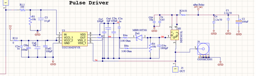
Hello,I have a circuit shown in the attached photo which basicly shows UCC5304 powering a mosfet using floating voltage.
My circuit basicly uses figure 22 of the attached datasheet.
I know that they put too much capacitors and i am sure i need the diode structrue.
basickly we put capacitors to to stabilise voltage supply and reduce noise.
any reccomendation regarding what capacitors to put in the structure?


Attachments

  • 1.png
    1.png
    52.5 KB · Views: 17
So far, there are already four threads discussing aspects of this switch configuration plus some more that are loosely related:

Some questions haven't been answered in the discussion, particularly: what are the switching speed requirements, why this circuit topology?
A PMOSFET driven by a level shifter is probably a better solution.
 
The problem I see is that the source impedance is never zero, yet there is no value stated on the schematic and the series R has a value of 0.

The ESR of each elliptical circle component is important to choose if you want to simplify the structure from 4 components to fewer values.

1719802236672.png
When we are new designers, we do not understand or appreciate that all capacitors have ESR and ESL but now are coached by TI Designer software to put the ideal passive component values on schematics, rather than LTspice does, without adding notes or part numbers or ESR values. These days it is critical to specify and choose these parts and show logic diagrams (aka schematics) because we need to appreciate the logic of component selections based on impedance ratios for attenuation, phase margin and damping factors in step response to pulse currents.
1719802781134.png


I understand your question about how to specify capacitor structures. In the old days when ESR was not widely published, we had to guess, so we assumed worst case and chose a capacitor every decade to keep the spectral impedance low in frequency, whether that was the standard 1 ohm or 100 mohm ort ultra low ESR values. Fundamentally, noise attenuation is all about Kirchoff's attenuation factors for apparent impedance from complex values. If you do not know you might find your example from 1 uF to 100 pF. This is great for VHF, and some UHF noise but even 100 pF is not ideal if you plan on attenuating 10 GHz crosstalk.

So although this is not an answer, it is just some advice for you to try to understand where and what your noise spectrum looks like and what power supply suppression ratio, (PSSR) that you expect and then what sensitivity to noise modulating your RF signal for sidebands before you choose attenuating components. Often a ferrite bead is as effective as a 100 pF cap yet in some cases a 33 pF is lower impedance than 100 pF cap depending on case size and microwave band.
 

LaTeX Commands Quick-Menu:

Similar threads

Part and Inventory Search

Welcome to EDABoard.com

Sponsor

Back
Top