Continue to Site

Welcome to EDAboard.com

Welcome to our site! EDAboard.com is an international Electronics Discussion Forum focused on EDA software, circuits, schematics, books, theory, papers, asic, pld, 8051, DSP, Network, RF, Analog Design, PCB, Service Manuals... and a whole lot more! To participate you need to register. Registration is free. Click here to register now.

UC3854 PFC controller working principle and IC block diyagram

Status
Not open for further replies.

ivan_mateo

Member level 1
Member level 1
Joined
Feb 11, 2019
Messages
40
Helped
1
Reputation
2
Reaction score
2
Trophy points
8
Activity points
385
Hi everyone,

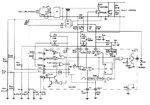
I am planning to design a not complicated PFC circuit and started from understanding of UC3854 inside block diyagram, working princible. But I can not figure how to some structure. As you can see in the below, pin8 connect to AC line and detect input signal after that it square the signal and connect multipler. Also, multiplier has other pins that pin6 and pin11. And this multiplier doing I=A.B/C. I stuck in there, what is the purpose of multiplier?
Ekran Alıntısı.jpg
 

Hi everyone,

I am planning to design a not complicated PFC circuit and started from understanding of UC3854 inside block diyagram, working princible. But I can not figure how to some structure. As you can see in the below, pin8 connect to AC line and detect input signal after that it square the signal and connect multipler. Also, multiplier has other pins that pin6 and pin11. And this multiplier doing I=A.B/C. I stuck in there, what is the purpose of multiplier?

View attachment 159166

UC3854 is a PFC controller IC employing Average current mode control. Output of the voltage error amplifier is divided by square of the average input voltage & the resultant gets multiplied by rectified input voltage signal. Squarer, multiplier & divider circuit plays a pivotal role . This extra circuitry keeps the gain of the voltage loop constant. If this circuit is not present, the loop gain would vary as square of the input voltage.

How????...

Let's assume that output of voltage error amplifier remains constant(No variation in Load) & input voltage is increased by 2 times .So EA output multiplied by average input voltage(I.e. A.B) doubles up but at the same time gets divided by square of the input voltage(C) so effectively resultant (Current programming signal)of A.B/C is reduced by half. So the effective input power remains constant.

Due to this, output of the error amplifier acts as a power control i.e. it controls the output power delivered to load.

Note:- if you want, You can refer to some of the old but well written documents by TI/Unitrode. They nicely explain about the complete operation. kindly, go through those before you start designing a PFC circuit.
 
Last edited:
read the original unitrode data sheets and app notes VERY CAREFULLY they tell you everything - if your level of engineering education is up to the necessary level for such a project as compensating a UPF booster.
 

UC3854 is same as LT1248 mostly...so to understand it, run the sim in ltspice that i attach
 

Attachments

  • LT1248 PFC AV MODE.zip
    185.4 KB · Views: 198
  • LT1248 vs UC3854.zip
    11.6 KB · Views: 211
UC3854 is a PFC controller IC employing Average current mode control. Output of the voltage error amplifier is divided by square of the average input voltage & the resultant gets multiplied by rectified input voltage signal. Squarer, multiplier & divider circuit plays a pivotal role . This extra circuitry keeps the gain of the voltage loop constant. If this circuit is not present, the loop gain would vary as square of the input voltage.

How????...

Let's assume that output of voltage error amplifier remains constant(No variation in Load) & input voltage is increased by 2 times .So EA output multiplied by average input voltage(I.e. A.B) doubles up but at the same time gets divided by square of the input voltage(C) so effectively resultant (Current programming signal)of A.B/C is reduced by half. So the effective input power remains constant.

Due to this, output of the error amplifier acts as a power control i.e. it controls the output power delivered to load.

Note:- if you want, You can refer to some of the old but well written documents by TI/Unitrode. They nicely explain about the complete operation. kindly, go through those before you start designing a PFC circuit.

Thank you. I think your comment seems from U134 Unitrode document. Yes, actually I understand your comment that how to control input power. If the input power goes double, multipler will help to circuit to draw half current with multipler. Therefore, input power will be balance. But normally in PFC circuit; there is a current detector and this detect zero crossing point, in zero point of line voltage, ICs duty cycle is full. And when the input line voltage is peak value, duty will be minimum. But this boundary current mode control. Due to inductor current has high peak, I think it is to convenient in high power application.

- - - Updated - - -

UC3854 is same as LT1248 mostly...so to understand it, run the sim in ltspice that i attach

Thank you. Also, I found UC3854 sub circuit in PSIM.
 
  • Like
Reactions: treez

    T

    Points: 2
    Helpful Answer Positive Rating
Hi Ivan
It is very conscientious of you to worry about the multiplier etc…and of course very interesting….but many can implement Average current mode boost PFC and not bother with how the multiplier is working.

If you look at the attached ltspice simulation, then you see a good deal of how the UC3854 works……all this attached Boost pfc does is use a constant off time controller (COT needs no mitigation for subharmonic oscillation).
There is simply an error amplifier which has a sinusoidal reference (derived from the post diode bridge bus voltage)….it then has its loop closed on the input current, so the input current has to follow the sinusoidal reference…….the circuit is forced to be with PFC.
..Note that no multiplier was needed here. None…So as you can see, average current mode PFC can be done without a multiplier….as long as the load is LED on constant max power…since LEDs clamp the vout to the total Vf.

The UC3854 is partly exactly the same as this…but UC3854 circuits most often do not conveniently have a constant LED load as does the attached……so there is a need for Vout regulation aswell………as such, the sinusoidal reference has to be “tempered” by the output from the output voltage error amplifier…..i am sure you would agree that this is an obvious requirement……………………..since the higher the vout is going…….the lower the input current needs to be to get it back into control…..so the sinusoidal reference needs to be mixed with the voltage error amplifier output….just as you see in the UC3854 block diagram…the multiplier bit is all about reducing line current distortion at light load……if you run an average current mode pfc at light load, you will see that the power factor detioriorates, and the line current can get badly distorted especially at the zero crossings…and the multiplier is partly about mitigating this to an extent.

BCM PFCs also have a problem in light load with detioriorating power factor, and they get round it by deliberately drawing more current at the zero crossings.
 

Attachments

  • Boost PFC LED.pdf
    24.3 KB · Views: 212
  • Boost PFC LED.txt
    12.3 KB · Views: 101

Status
Not open for further replies.

Part and Inventory Search

Welcome to EDABoard.com

Sponsor

Back
Top