Continue to Site

Welcome to EDAboard.com

Welcome to our site! EDAboard.com is an international Electronics Discussion Forum focused on EDA software, circuits, schematics, books, theory, papers, asic, pld, 8051, DSP, Network, RF, Analog Design, PCB, Service Manuals... and a whole lot more! To participate you need to register. Registration is free. Click here to register now.

[ARM] UART not responding under OSC BYPASS Mode

Status
Not open for further replies.

Prototype21

Junior Member level 1
Joined
Mar 3, 2020
Messages
15
Helped
0
Reputation
0
Reaction score
0
Trophy points
1
Activity points
121
Hello Guys,

I am trying to setup UART under oscillator bypass mode in STM32f446RE Nucleo Board. I have created a new project in CubeIDE with UART under Asynchronous mode. I have commented out the SystemClock_Config and written my code for oscillator bypass mode even though everything can be done via code generation tool ( Part of learning ). But UART is not responding. Please find the below-attached project.


Code:
char data[] = "Hello World\r\n";
     
    int main(void)
    {
      HAL_Init();
      //SystemClock_Config();
     
      RCC_OscInitTypeDef Osc = {0};
      RCC_ClkInitTypeDef Clk = {0};
     
      Osc.OscillatorType = RCC_OSCILLATORTYPE_HSE;
      Osc.HSEState = RCC_HSE_BYPASS;
      HAL_RCC_OscConfig(&Osc);
     
      Clk.ClockType = RCC_CLOCKTYPE_SYSCLK | RCC_CLOCKTYPE_HCLK | RCC_CLOCKTYPE_PCLK1 | RCC_CLOCKTYPE_PCLK2;
      Clk.AHBCLKDivider = RCC_SYSCLK_DIV2;
      Clk.SYSCLKSource = RCC_SYSCLKSOURCE_HSE;
      Clk.APB1CLKDivider = RCC_HCLK_DIV2;
      Clk.APB2CLKDivider = RCC_HCLK_DIV2;
     
      HAL_RCC_ClockConfig(&Clk, FLASH_ACR_LATENCY_0WS);
     
      __HAL_RCC_HSI_DISABLE();
     
      HAL_SYSTICK_Config(HAL_RCC_GetHCLKFreq()/1000);
      HAL_SYSTICK_CLKSourceConfig(SYSTICK_CLKSOURCE_HCLK);


      MX_GPIO_Init();
      MX_USART2_UART_Init();
     
      while (1)
      {
       HAL_UART_Transmit(&huart2, (uint8_t*) data, sizeof(data), HAL_MAX_DELAY);
      }
    }

Please find the attached project.
 

Attachments

  • RCC_UART.zip
    6.8 MB · Views: 184

Please elaborate on "not responding" (which is a totally inadequate problem description).
What does it do that you don't expect? What doesn't it do that you do expect? Is the problem on the Tx or the Rx side - how do you know?
In bypass mode, you need an external oscillator: how have you supplied that and what is its frequency?
One point to note: UARTs need a clock that is within +/-2% of the nominal frequency to work. Otherwise you can get framing and parity errors on the receiving side. This is a common source of problems.
Susan
 

By not responding I mean it's not giving me on the serial monitor. I am using a stm32f446re nucleo board. In this board, the stlink provides an 8 MHz signal which I am trying to use in bypass mode. I am trying to print a text on the serial monitor in bypass mode.

My HCLK is 4Mhz & baud rate I am using is 115200. How to calculate the baud in st microcontroller?
 

if you are using CubeMX then setting the BAUD rate is trivial - it is directly set in the UART configuration window.
Check in the clock tree configuration that you have the oscillator set up for USART2 (which you appear to be using). I would start by using the default HSE oscillator to get things working in the first place. Later you can switch to the external clock but at leat you know that everything else is working correctly.
I suggest that you look at some of the (many) tutorials on the Internet about. I have also purchased the "Mastering STM32" book by Carmine Noviello which I find useful (but be aware that there are errors in the early version I have and the grammar is sometimes a little awkward). There is also a web site associated with the book to find out about any mistakes you think you have found.
 

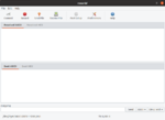
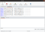
I have tried different baud rate, but I don't see any change. Also, I have noticed something weird in my serial monitor. It's not responding in ASCII Mode but responding in HEX Mode in my serial monitor.

serial1.png

In Hex View:

seria2.png

After some debugging, I found that when the function HAL_RCC_ClockConfig(&Clk, FLASH_ACR_LATENCY_0WS) exit, the value of SystemCoreClock changes from 16000000 to 12500000. But I am expecting an HCLK of 4Mhz.

clk.png
 

I have tried different baud rate, but I don't see any change.
What change were you expecting? Change to what?
As for the change in SystemCoreClock, what value do you expect to see if HCLK is 4MHz?
I don't mean to be rude but you really need to start giving us better information if you expect any real assistance.
Susan
 

Status
Not open for further replies.

Part and Inventory Search

Welcome to EDABoard.com

Sponsor

Back
Top