cupoftea
Advanced Member level 5

Hi,
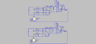
We are doing an offline 2 Tran Forward, 120kHz, 24vout, 130Wout. No PFC.
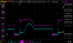
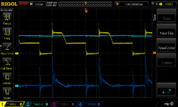
At 240VAC in, we see the following two VDS waveforms for top and bottom FETs.
(Red = Low FET Vds, Blue = Top FET Vds).
The Low FET is directly driven, but the Hi FET is driven via a gate drive transformer.
As expected, and can be seen, the Low FET turns off first.
And as expected, and can be seen, the Low FET also turns off first.
At turn off, we might expect each Vds to go to max...since the two reset diodes should both be conducting.
But as can be seen, only the low FET takes the full rail voltage. For some reason, the reset diode "below" the Hi FET
doesn't conduct, as is obvious from the attached. Instead, we first see some ringing, which is obviously the leakage inductance ringing out.
When both traces go horizontal, that is when the primary has demagnetised, and then both secondary diodes take part
in the conduction of the falling output inductor current.
Its almost as if the top FET is conducting the resetting magnetising current by being in the linear region.
Would you agree?
Though i am looking into whether there is some "situation" here with the leakage currents of the two diff probes that are used.
The SMPS is supplied via an isolation transformer.
We are doing an offline 2 Tran Forward, 120kHz, 24vout, 130Wout. No PFC.
At 240VAC in, we see the following two VDS waveforms for top and bottom FETs.
(Red = Low FET Vds, Blue = Top FET Vds).
The Low FET is directly driven, but the Hi FET is driven via a gate drive transformer.
As expected, and can be seen, the Low FET turns off first.
And as expected, and can be seen, the Low FET also turns off first.
At turn off, we might expect each Vds to go to max...since the two reset diodes should both be conducting.
But as can be seen, only the low FET takes the full rail voltage. For some reason, the reset diode "below" the Hi FET
doesn't conduct, as is obvious from the attached. Instead, we first see some ringing, which is obviously the leakage inductance ringing out.
When both traces go horizontal, that is when the primary has demagnetised, and then both secondary diodes take part
in the conduction of the falling output inductor current.
Its almost as if the top FET is conducting the resetting magnetising current by being in the linear region.
Would you agree?
Though i am looking into whether there is some "situation" here with the leakage currents of the two diff probes that are used.
The SMPS is supplied via an isolation transformer.