Continue to Site

Welcome to EDAboard.com

Welcome to our site! EDAboard.com is an international Electronics Discussion Forum focused on EDA software, circuits, schematics, books, theory, papers, asic, pld, 8051, DSP, Network, RF, Analog Design, PCB, Service Manuals... and a whole lot more! To participate you need to register. Registration is free. Click here to register now.

two small peaks besides the fundamental frequency

Status
Not open for further replies.

shanmei

Advanced Member level 1
Joined
Jul 26, 2006
Messages
430
Helped
8
Reputation
16
Reaction score
8
Trophy points
1,298
Location
USA
Activity points
4,496
I have a signal, and I do the SFDR simulation. I found two peaks as the figures show near the fundamental frequency. What's that? Thanks.
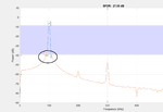
1.png

The original time domain signal is shown as bellowing figure, it changes its amplitude at around 4.3e-4 second. Can the changing amplitude cause the two peaks on the freuency domain? Thanks.

2.png
 
Last edited:

Probably mix-tones, their offset from the fundamental
is the modulating frequency. Looks like ~ 5kHz. Also
looks like you want to play some with your resolution
bandwidth, too much rounding of what ought to be
narrow.
 

The original time domain signal is shown as bellowing figure, it changes its amplitude at around 4.3e-4 second. Can the changing amplitude cause the two peaks on the frequency domain? Thanks.
A single amplitude step doesn't transform to discrete spectral lines. But we need to know the FFT window used when calculating the spectrum for an exact analysis.

Performing the SFDR measurement with an amplitude step seems questionable in any case.
 
Hi

The FFT output is always like the signal (in time domain) is repeating.
Imagine an identical signal is appended to the current signal (window).
Now it seems that the step is repeating.

The signal then shows like an amplitude modulated carrier.
The modulation signal (here it looks like a square wave) with it´s frequency components will appear right and left to the carrier frequency.

Maybe this is what you see in your picture.

If the bottom window is the complete FFT window, then we see a total time of 800us. This gives a repeat frequency of 1250Hz.
But the difference frequency seems to be around 8kHz...so it doesn´t fit.


Klaus
 
Status
Not open for further replies.

Part and Inventory Search

Welcome to EDABoard.com

Sponsor

Back
Top