Vermes
Advanced Member level 4

The system is designed to control the external device of alternating current based on temperature readings from two external thermometers.
The principle of operation is simple: uP reads the temperatures from thermometers and if the difference exceeds a set value, the external device is activated. The system has many options adjustable with four control buttons located just below the screen.
Functions:
- the ability to set the temperature difference
- the width of the hysteresis
- the time of switching on the device
- the time of switching off the device
- the minimum temperature
- the real time clock
- ability to store the maximum temperature of each sensor
- watchdog
- RTC 3V battery-buffered
- storing set parameters in non-volatile EEPROM memory
Construction:
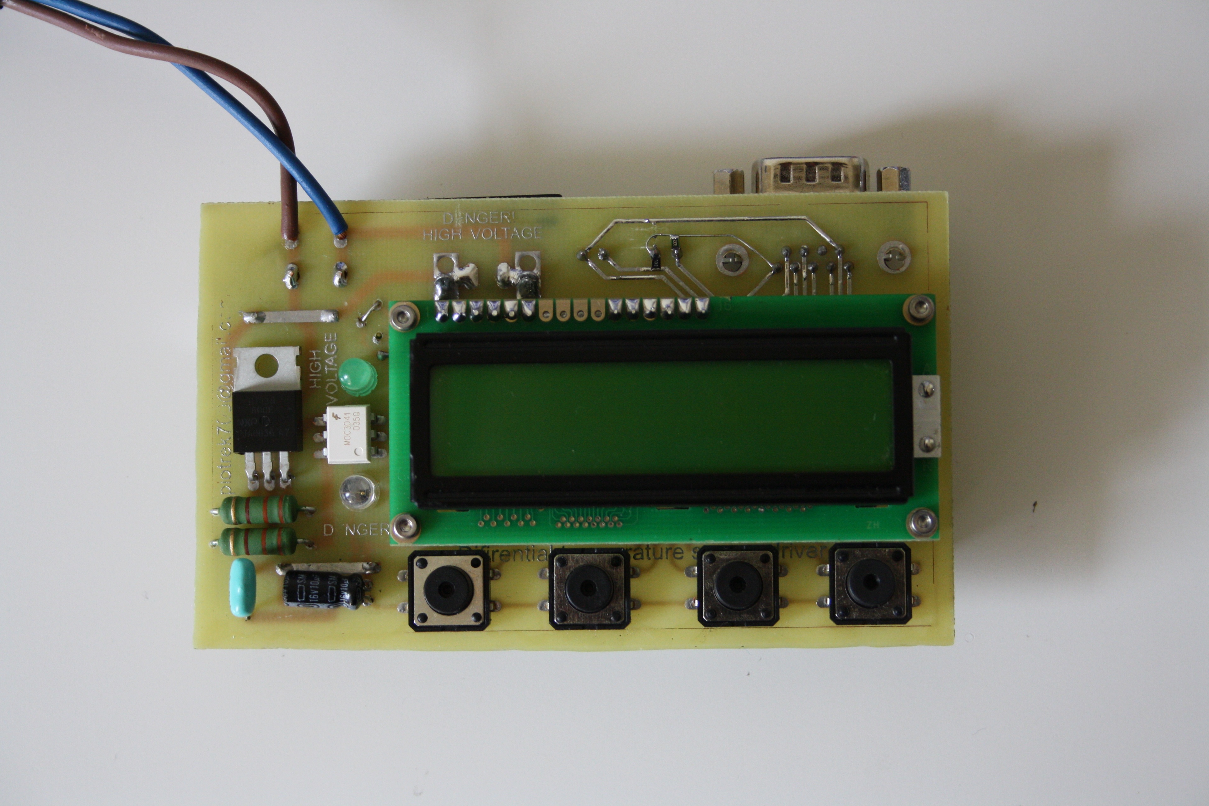
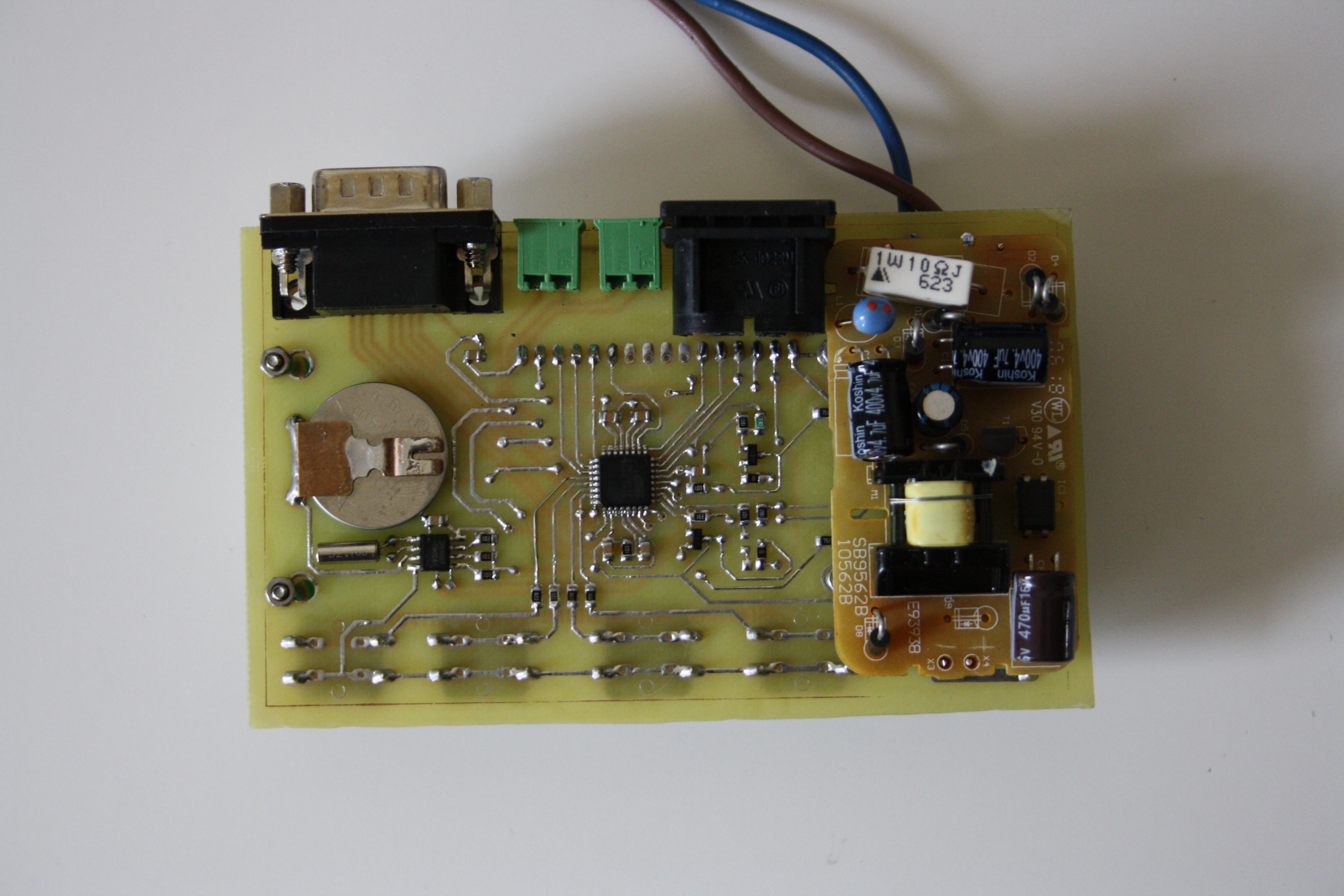
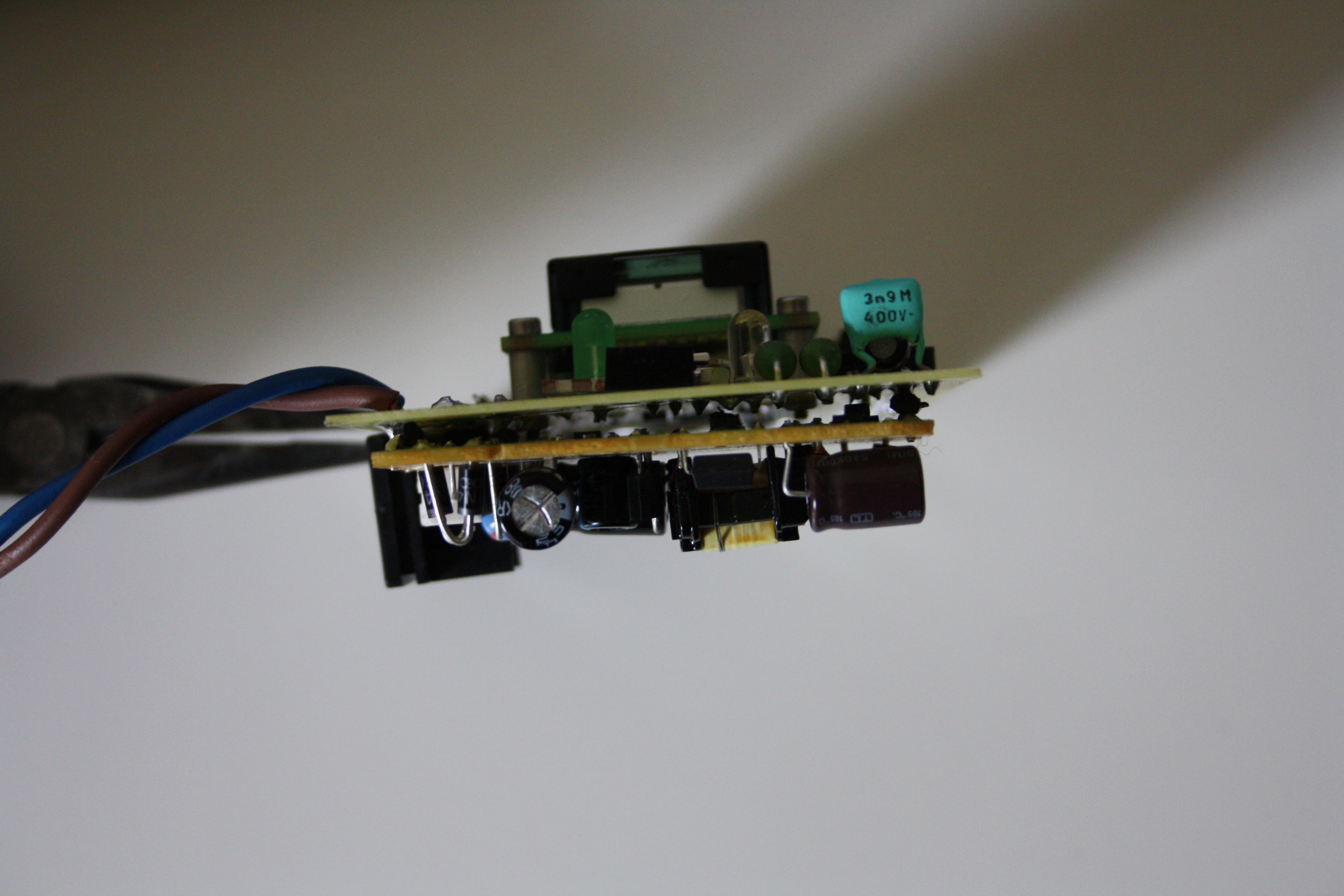
The device is based on the AVR processor Atmega168 clocked with internal oscillator 1MHz. The processor works with the LCD display WC-1602A0 2x16 characters on the driver HD44780, specifically on the clone of that driver - KS0066U. Dallas sensors 18B20 are the thermometers connected through the 1-Wire interface. The system also has a DS1307 real time clock that communicates using the I2C interface. RTC is clocked by an external quartz 32.768kHz and has a battery to maintain time with power off. The role of the element that controls the high voltage external device plays TRIAC BT138 isolated by optocoupler MOC3041. Two control diodes – the green one indicates the connection to the controller power, while the red LED indicated the operation of an external device. The system is powered by a switching mode power supply (5V).
The software for AVR was written in C in AVR Studio 4. The system has an implemented watchdog support and read of the set parameters to the EEPROM memory.
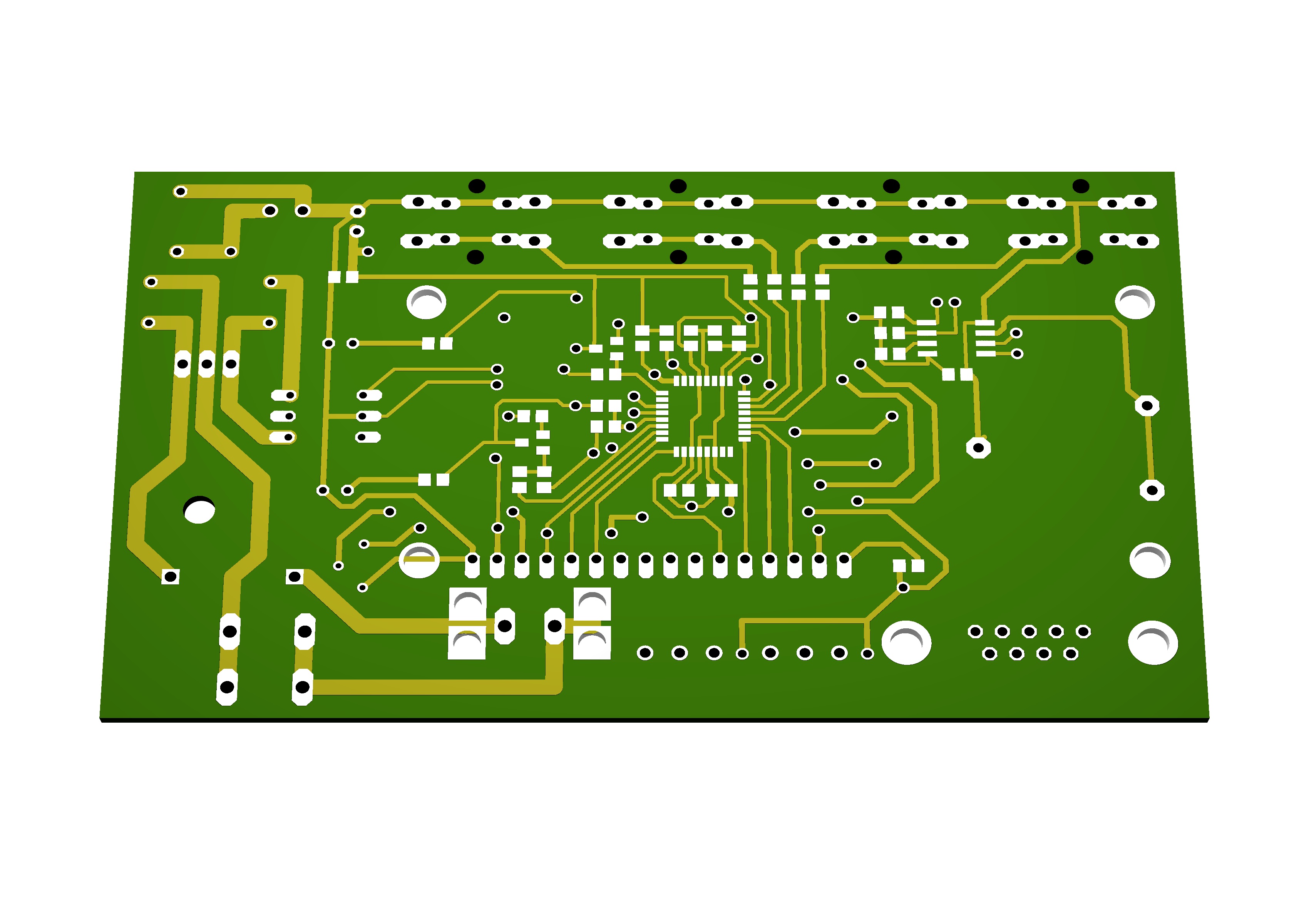
Below there are some pictures.


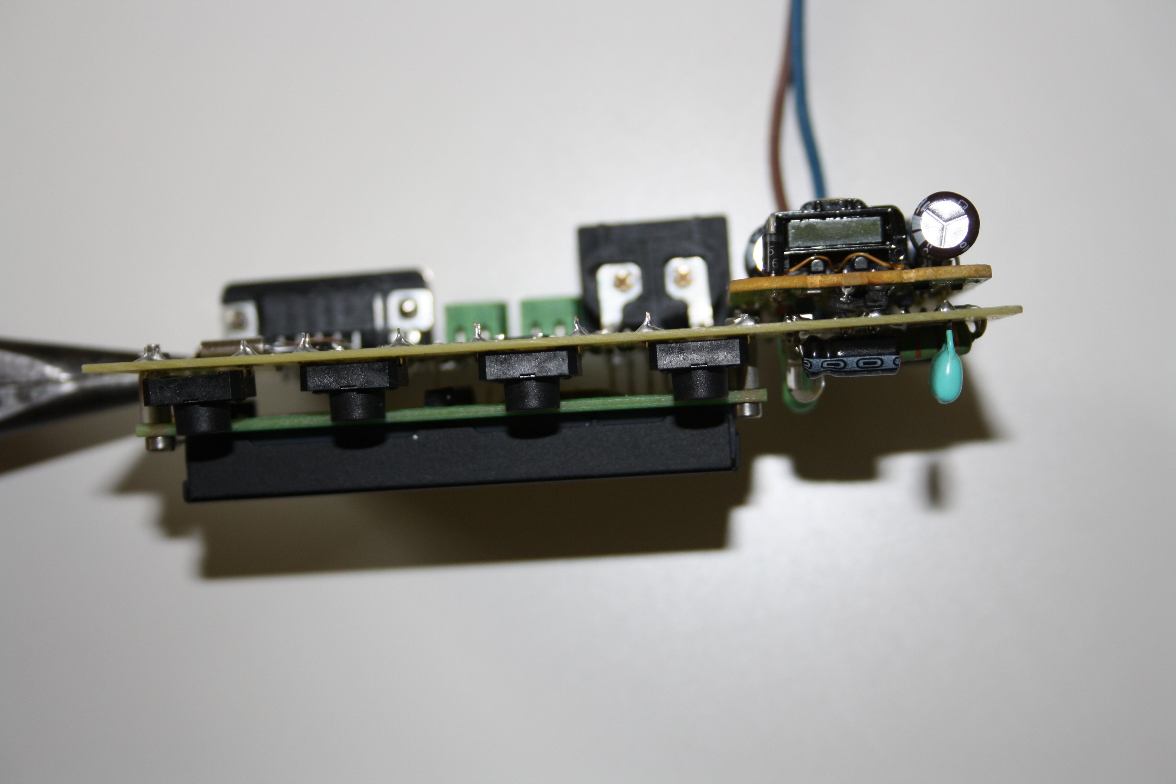
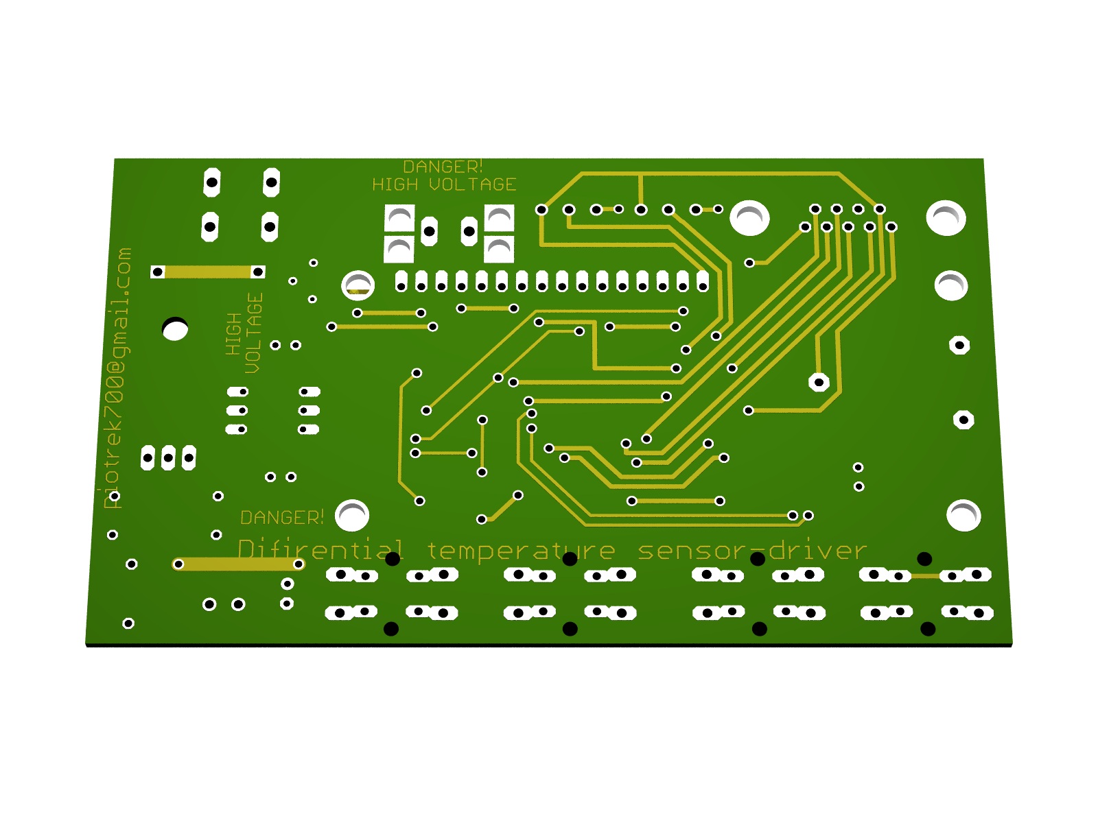

WARNING! The system voltages are hazardous to human health or life!
Link to original thread (useful attachment) – Dwuczujnikowy regulator temperatury v2.0