gres
Full Member level 4

Tsting board Atmeg32

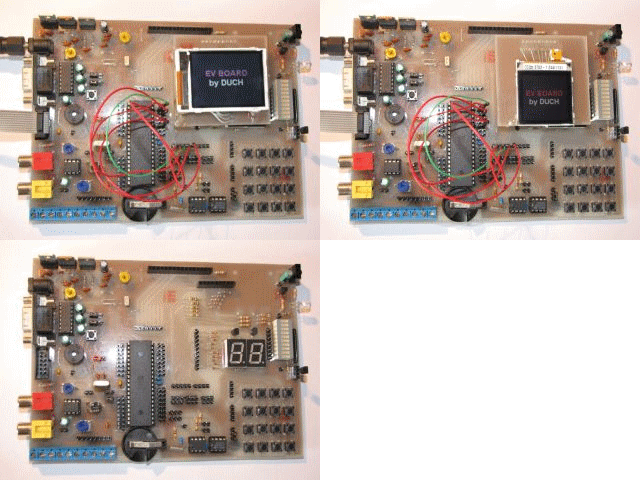
I would like to present testing board for my brother.Heart of the system is Atmeg32 or 16 ( in this case it is atmeg32). It consist possibility of working with those displays:
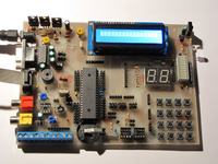
LCD HD44780,
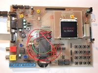
PCF8833 (nokia 6100/6610i),
LSO20 (siemens S65/cx70),
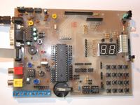
Two 7-leg LED displays
LED ruler
Matrix keyboard 4x4 allows to switch it to 4x1mode with 4 buttons seamless to mass.
I used DS1307 (RTC) system with battery power backup, and slot to outside memory EEPROM. Both chip sets are connected to Atmega wia 2 jumpers SDA and SCL. Additionally you can connect bend resistors also via jumpers.
Line input (yellow chinch ) allow to measuere voltages at operational amplifier LM358 or through potentiometer.
Line output (red chinch) is an output with maximum frequency 7 kHz, gain by LM358
RS232 slot through ST232 system allow to communicate with PC (disconnect by jumpers)
Board consist transmitter and reference of irda and buzzer.
LCD display HD44780 consist jumper that has pinRW to mass, so while writing soft you can use R/Wpin.
When Power for device is 5V it goes from programmer.
Voltages 3V 6V and 10V are supplied by outside power supply, via LM317 and LM7806 systems.
At the board I placed slot for temperature sensor DS18b20.
I used screw fastening ARK that allow to connect outside elements.
Costs are very small especially that most of elements I had.
Original text comes from : https://www.elektroda.pl/rtvforum/topic1435311.html?sid=dda5bbd3ed764b4b9059d01e572b5702


