Continue to Site

Welcome to EDAboard.com

Welcome to our site! EDAboard.com is an international Electronics Discussion Forum focused on EDA software, circuits, schematics, books, theory, papers, asic, pld, 8051, DSP, Network, RF, Analog Design, PCB, Service Manuals... and a whole lot more! To participate you need to register. Registration is free. Click here to register now.

TSMC 65NM BJT cell

Mounikap

Newbie level 4
Newbie level 4
Joined
Aug 7, 2024
Messages
7
Helped
0
Reputation
0
Reaction score
0
Trophy points
1
Activity points
56
Hi,

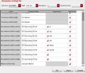
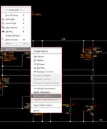
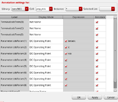
I am designing the BGR in TSMC 65nm. And I am using pnp_mis standard cell but after simulating i couldn't able the DC operating points of BJT. So can anyone please guide me how can i enable the DC operating points in cadence window ?

And can anyone please tell me can i use pnp or pnp_mis standard cell fir BJT ?

Pnp_mis.png
 
And can anyone please tell me can i use pnp or pnp_mis standard cell fir BJT ?
As I remember, pnp_mis is standing for a mismatch support in BJT model (so it is important to use this model while running Monte-Carlo simulations). Since you are designing BGR, it is very important to use pnp_mis in order to get a valid simulation results.

Regarding the DC operating points, did you enable "Save DC operating point" checkbox in your ADEL analysis?

1723798521027.png
 
Yes, I have enabled the "Save DC operating point" in ADEL analysis. But still i can't see the region of the BJT.

One more thing is that, here for "pnp_mis" I couldn't able to see the option of multiplier. But for "pnp" i can see and change the multiplier. Do we set any settings for pnp_mis in cadence. Can anyone please help me regarding this issue. Please check the images below for your reference.

Pnp_mis_65.png
Pnp_65.png
 
Yes, I have enabled the "Save DC operating point" in ADEL analysis. But still i can't see the region of the BJT.

One more thing is that, here for "pnp_mis" I couldn't able to see the option of multiplier. But for "pnp" i can see and change the multiplier. Do we set any settings for pnp_mis in cadence. Can anyone please help me regarding this issue. Please check the images below for your reference.
It seems like you have enabled "DC Voltages, Currents" in annotations instead of DC Operating points. Try to select "DC operating points" and it should work.
Regarding the multiplier - you can use Q2<0:7> notation instead. Simply open the parameters of your cell, change "Apply to" to "selected only" and type necessary number of devices in instance name.

Screenshot 2024-08-19 082938.png
 
I have clicked on "DC operating point". But still i can't see the operating regions on the cadence window. But for MOSFET, i can able to see it. But not for the BJT. Please find the below screenshots for your reference.

And the multiplier is working. I can able to change the Instance name.

Thank you so much for responding.
 

Attachments

  • Pnp_mis_65_DCoperating points_3.png
    Pnp_mis_65_DCoperating points_3.png
    46.2 KB · Views: 32
  • Pnp_mis_65_DCoperating points_2.png
    Pnp_mis_65_DCoperating points_2.png
    46.5 KB · Views: 27
  • Pnp_mis_65_DCoperating points_1.png
    Pnp_mis_65_DCoperating points_1.png
    87.4 KB · Views: 32
I have clicked on "DC operating point". But still i can't see the operating regions on the cadence window. But for MOSFET, i can able to see it. But not for the BJT. Please find the below screenshots for your reference.

And the multiplier is working. I can able to change the Instance name.

Thank you so much for responding.
Hm, that's weird.
Maybe try to save currents in your circuit by navigating to Outputs -> Save all. Since BJT operates with currents, it might help.
1724138952368.png
 
Thank you for the reply. I have tried the above steps. But still I couldn't see the "DC operating regions" of the BJT. I can able to see the "DC operating regions" for "pnp" and MOSFET without following above steps. But the problem is with "pnp_mis". Do we need to enable some settings specially for "pnp_mis" ? Because all the DC operating points of "pnp_mis" are disabled (not highlighted) in annotations.
 

Attachments

  • Pnp_mis_65_DCoperating points_2.png
    Pnp_mis_65_DCoperating points_2.png
    46.5 KB · Views: 22
The last thing to try is to add DC operating point parameters of interest to your outputs in ADEL/XL using calculator. If this doesn't work, I would simply use "pnp" for circuit tuning and debugging; once everything is ready (your circuit is stable across PVT), simply replace your "pnp" with "pnp_mis" with the same parameters (multipliers, size etc.) and run MC.
P.S. When replacing your devices, I would recommend to select a test case, simulate it and get output waveforms; then repeat same simulation after device replacement and append new waveforms to check that there is no difference.
 
But "pnp" and "pnp_mis" are different devices right ? I tried the above method. When i checked with "pnp" all the mosfet are in saturation and the output voltage is 0.6V (desired reference voltage). But when i replaced pnp with pnp_mis with same parameters then few mosfets are not in saturation and the output is 0.2V.
 
But "pnp" and "pnp_mis" are different devices right ? I tried the above method. When i checked with "pnp" all the mosfet are in saturation and the output voltage is 0.6V (desired reference voltage). But when i replaced pnp with pnp_mis with same parameters then few mosfets are not in saturation and the output is 0.2V.
Should be absolutely same thing, except MC support for pnp_mis, so I suspect some mistake happen while you were replacing the devices.

You can check this by:
1. Taking "pnp" and "pnp_mis" and exporting them to the layout. There should be no difference in layers, size, etc.
2. Creating a simple circuit where you bias both "pnp" and "pnp_mis" in the same conditions and the simulating and measuring the outputs. They also suppose to be identical.
3. Checking the description in TSMC documentation.
 

LaTeX Commands Quick-Menu:

Similar threads

Part and Inventory Search

Welcome to EDABoard.com

Sponsor

Back
Top