Continue to Site

Welcome to EDAboard.com

Welcome to our site! EDAboard.com is an international Electronics Discussion Forum focused on EDA software, circuits, schematics, books, theory, papers, asic, pld, 8051, DSP, Network, RF, Analog Design, PCB, Service Manuals... and a whole lot more! To participate you need to register. Registration is free. Click here to register now.

Trying to control 4-digit LED display with thumb-wheel

Status
Not open for further replies.

skarkowtsky

Advanced Member level 4
Full Member level 1
Joined
May 25, 2016
Messages
109
Helped
0
Reputation
0
Reaction score
0
Trophy points
16
Activity points
1,076
Hi everyone-

My name is John--I'm a new forum member. A bit about me, I'm a graphic designer and amateur prop maker, though I don't know anything about electronics. Here's what I'm trying to achieve.

I'd like to use a 4 digit thumb-wheel switch (Digitran 23000) to set the numbers on a 4 digit LED display. The numbers should remain static. I don't want a clock or countdown.

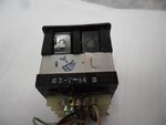
Thumb-wheel:
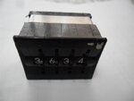
1.jpg

4.jpg

6.jpg

Also, is it possible for (1) thumb-wheel switch to control (12) led readouts, independent of each other? So, each displays a different 4 digit number?

I'd appreciate any help you can offer.

Thanks!
John

- - - Updated - - -

Allow me to give a detailed explanation of what I'm hoping for. Then we can determine if it can be achieved.

Here is what I imagine:

Master power switch, connected to two 9 volt batteries wired in parallel. This supplies power to the (12) 4-digit LED displays, thumb-wheel, and whatever circuitry is required.

Each of the (12) LED displays has its own three-position ON/OFF/ON toggle switch. Wire those switches so the up position ON is now OFF, cutting power from the Master power switch. The center OFF is now ON, but not connected to the Master power switch--connected to the thumb-wheel. So, the LED display is not on, but the board is getting a signal and unique 4-digit number that I dial in on the thumb-wheel. The down position ON is connected to the Master power switch, which supplies power to the display to reveal the unique 4-digit number I assigned to that specific module.

I think this means that each of the 12 LED displays requires memory and a burn-in.

This also means that if all LED modules had their toggle switches set to the center position, I would be able to assign the same 4-digit number to all, and would be viewable if I threw all the toggles to the down position. Of course, I wouldn't do that, I want each to have a unique 4-digit number.

Does this make sense?
 
Last edited by a moderator:

you can used CD4543 BCD to decimal decoder IC provide the thumb wheel out to the BCD input of the chip and connect the 7 segment display to the output of the CD4543
 

Yes it makes sense.

As Fragrance says, you will need a BCD to seven segment decoder and driver chip to convert the thumb wheel data into a form that lights up the correct segments of each display.

And each display will require a four bit latch (memory) to drive each decoder chip.
As there are four digits per display, it will require eight chips per display.

Twelve displays make 96 integrated circuits, so there is going to be quite a lot of parts and wiring up involved.

Two 9v batteries are not going to last long driving 48 seven segment displays.
Probably only a very few minutes at most.
 

This is a classic case for using a dedicated display driver and ideally a small microprocessor. I think it can be done in 7 ICs and no memory outside that already present in them.

Using the BCD (the code from the switch) and decoding it to 48 7-segment displays with memory (latches) using 7-segment decoders would take around 50 ICs. I agree that a better power source is essential, if an '8' is displayed (digit needing most segments simultaneously) and each segment draws say 10mA, the total current would be 48 * 8 * 0.01 = 3.84 Amps, that's far more than small 9V batteries can cope with, you are in the realms of big car batteries if you want any significant operating time.

My 7 IC idea is six MAX7219 drivers, each driving eight digits and one small PIC to initialize them, decode the switch and serialize the data. Because it would multiplex the digits, only six would be active at a time and the current consumption would drop to about 0.5 Amps.

Brian.
 

Hi everyone-

Thank you for the informative responses. Some of the technical terms are a bit over my head, but I'm following. It seems that if this were laid out on a bench, it would be a sprawling circuit. My dad is technical, and if he had schematics, he could put together what you're referring to. He isn't certain where to start, but is going to help me on this project based on your recommendations.

The scale of this circuit is important to me, and I'd like to keep it as small as possible. I'm not sure if this is the right forum to ask about the following, but would an Adruino controller be able to power 12 led display boards while keeping the size down? If so, would we be able to wire the thumb-wheel switch into the Adruino to control the numerals?

I'm open to making the circuit based on your suggestions within if we can develop a way to keep the scale down.

Thanks for everything thus far.


Cheers,
John

CD4543 have latching function so you do not required latch chip, max7219 is also good idea but required a pic interface or Adruino interface there are plenty of example on the web controlling Max7219 with Adruino you can check at sparkfun web page there are display driver using Max7219 you can downlaod code schematic and build info if you want to do it your self or order the complete kit
 

There are basically two completely different approaches to this.

The nuts and bolts "hardware" solution.
Or using a computer chip and some software to do much of it.

Both approaches have advantages and disadvantages.
Which you choose depends on your own personal preference.
 
Last edited:

Hi everyone-

My dad and I have decided to go the CD4543 BCD route. We are wondering if some would kindly advise how to wire this so we can assign unique 4 digit numbers to each of the 12 LEDs independently.

How can we engage and disengage the LED displays from the thumbwheel switch with 12 toggle switches, 1 per LED display?

Thanks!
John
 

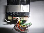
Looking at your photograph of the back of your thumbwheel unit...
It has many metal tabs. My hunch is they are organized in sets of 4 (plus a fifth wire as a common). Each set of 4 sends BCD (four hi or low signals). I think you can send these to the 4543 inputs (ABCD). The 4543 drives the 7-segment display.

You'll have four 4543 IC's. As a first step, make sure you can get four 7-segment displays to produce the same four numbers as are on your thumbwheels.

Your OP talks about re-wiring the innards of toggle switches. This sounds like a job for the tiniest tools, and it assumes you can pry apart the switch and put it back together, with absolute precision. This does not seem possible.

To select which of the four 4-digit panels receives thumbwheel data, press one of 4 switches (as you describe). This sets the states in a network of logic gates, and steers thumbwheel data to the desired set of 4543's. It should work like multiplexing.
 
Thanks! What do you think of the following?

There are 4 digits on the thumbwheel, each digit has 4 outputs, for a total of 16 outputs to one set of 4 BCDs to drive one 4 digit LED display.

So, I'm thinking:

I use an ON/ON/ON toggle switch for each of the LED readouts.

One position allows the BCDs to receive the signal from the thumbwheel switch, but the BCD is not connected to the LED readout.

A different position on the toggle now connects the BCDs to the LED readout while disengaging the BCDs from the thumbwheel switch.

I think I can do this by inserting a 16 position DIP switch in between the thumbwheel and toggle to act as a junction between the thumbwheel and the BCDs that can be independently turned on and off.

So, if I repeat this 11 more times, all of the BCDs will receive the same 4 digit number, but nothing will be displayed. If I throw only 1 toggle, that number will appear because it now connected that LED readout to its BCDs and is simply displaying what is stored in those BCDs memory.

Moreover, if I were to throw a second toggle somewhere else, that LEDwould display the same number as the first.

BUT, if I were to change the number on the thumbwheel before throwing the second toggle, that new number would display on the second LED because it is also just displaying what is burnt into the memory of its own BCDs.


Am I onto something?

Thanks!
John
 

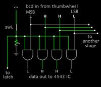
Here's a simple selector network. The switch is closed, causing incoming data bits (hi or low) to be sent to the 4543. With the switch open, all outputs are low.


The latch signal may need to be inverted, depending on what works with the 4543. You may need to arrange for the latch to operate independently of the data, to avoid the uncertainty of data changing simultaneously as you activate the latch.

You'll need 16 of the above schematic. This makes 64 'AND' gates. Possible some invert gates. Etc. (This concept is long the lines of dozens of IC's mentioned in post #4.) Of course you only need 4 manual switches, as you stated.

It might be possible to condense the concept to a simpler topology. Example, there may be a Data Selector IC available, to combine functions, and make your job easier.

- - - Updated - - -

Possible switching IC: hex 3-state bus driver, 74LS367. You wouldn't need 16, but some lesser number, 11 maybe.
 

Thanks for taking the time to diagram. Unfortunately, this is all over my head. I was hoping someone here could draw up the complete diagram/schematic and also list all necessary components we need to achieve this.

Unfortunately, this project is too big for me to go it alone.
 

So we try going down a path or two, and we may decide it's not what we want, nevertheless it can lead to clarification. So now the question comes up: Do you need all that switching? Why not fan out thumbwheel data to all four 4543's simultaneously? When you want to accept a 4-digit readout at a particular 7-segment display, then flip a switch activating a latch (that is, four latches associated with that 7-segment display). Then that 4-digit number is locked into those 7-segment displays.

This implies you can get by without 64 'AND' gates.

I would draw up a simulation but Falstad's simulator does not contain 4543 nor 4511 IC's.

In reality that would be 16 of 4543 connected directly to the thumbwheel outputs. This still appears unavoidable.
 

Why not fan out thumbwheel data to all four 4543's simultaneously? When you want to accept a 4-digit readout at a particular 7-segment display, then flip a switch activating a latch (that is, four latches associated with that 7-segment display). Then that 4-digit number is locked into those 7-segment displays.

Sincerely, excuse my ignorance, but I think this is what I was trying to describe early this morning. I don't even know what a latch is, or that I needed 1 per BCD. I think I'm following what latch does now.

What I want, and I don't care how I achieve it, is to be able to assign individual 4 digit numbers to each of the 12 LED displays with (1) 4 digit thumbwheel switch. Each with their own toggle switch to turn independently on and off at my discretion.

If we can somehow use the toggle switches to both engage and disengage the thumbwheel switch from the individual LEDs as to avoid a single 4 digit number from crossing over and displaying on more than one LED display, let's do it.
 
Last edited:

A latch has data inputs (from your thumb wheels) and data outputs (that drive the display, plus a "control input pin".

When the control pin is in one logic state, the outputs always follow the inputs.
In this condition the display will show whatever is set on the thumb wheels.

If the control pin moves to the other state, the outputs of the latch "lock" and remember whatever data is there. The outputs then stay fixed and constant, even though the inputs from the thumb wheels can be changed to something different.

Tere are several chip types that combine both a "latch", and a decoder driver to dive your seven segment displays. You will need one of these for each digit.

Here is a data sheet on the Motorola MC14495 which is a fairly typical device of this type:
http://pdf.datasheetcatalog.com/datasheet/motorola/MC14495P1.pdf
 

Sincerely, excuse my ignorance, but I think this is what I was trying to describe early this morning. I don't even know what a latch is, or that I needed 1 per BCD. I think I'm following what latch does now.

Yes, you were on track with the easiest approach. It is acceptable for all led's to reflect thumbwheel values simultaneously. (My post #12 went down the difficult path, because I thought you wanted only one set of led's to reflect thumbwheel values at a time.) When you want a set of 4 led's to lock onto a value, just flip the switch to enable its latch.

I also forgot you want to display three (not four) 4-digit numbers. (Where I say 16, it should say 12. Where I say 64 it should say 48.)

Anyway what I said is inferior to post #4. A multiplexing IC is an advantage because it is like several 4543's combined. It simplifies your wiring. And multiplexing saves power. Post #4 describes such an IC, the MAX7219. It comes up most often in an internet search. It can drive 8 digits, but you only need to use 4. There are IC's that drive 4 digits, but they do not necessarily multiplex.

- - - Updated - - -

I have not used the 7219. Above posts suggest it needs a PIC or Arduino.
 

Status
Not open for further replies.

Part and Inventory Search

Welcome to EDABoard.com

Sponsor

Back
Top