snafflekid
Full Member level 4

Hello RF gurus,
I should start by saying that I am trying to make insertion loss measurements on an analog switch in the 1 to 3 GHz range.
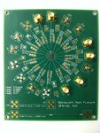
I have a PCB fixture that uses an SMA connector followed by a microstrip to connect to the pin on a soldered package. This PCB also includes two separate microstrips that I assume are used for TRL calibration. The first calibration microstrip is the length of 2 microstrips used in the fixture. I assume this is used to perform the THRU test. The second calibration strip is about half the length of the first calibration strip. Would this be used for the LINE test? I don't have the board in front of me now so I cannot say what the precise lengths of these two calibration strips are. Regarding the REFLECT test, can I connect the test port to one end of the LINE strip and leave the other end of the line strip open?
I have been reading much about the subject, but these details are eluding me.
Thank you!


