Continue to Site

Welcome to EDAboard.com

Welcome to our site! EDAboard.com is an international Electronics Discussion Forum focused on EDA software, circuits, schematics, books, theory, papers, asic, pld, 8051, DSP, Network, RF, Analog Design, PCB, Service Manuals... and a whole lot more! To participate you need to register. Registration is free. Click here to register now.

Triangular waveform generator for IC implementation

Status
Not open for further replies.

viperpaki007

Full Member level 5
Full Member level 5
Joined
Jul 2, 2008
Messages
274
Helped
11
Reputation
22
Reaction score
8
Trophy points
1,298
Location
Finland
Activity points
3,437
Hi,

I need to make a triangular waveform generator at 2.5MHz with 0 and 1.2V positive and negative voltages. Most of the circuits which i see in literature are made from opamp integrator. I don't want to use opamp integrator circuit because they use resistor to control triangle waveform ramp and it is quite hard to make precise resistors on IC. Can somebody suggest a triangular waveform generator suitable for IC implementation.

regards
 

You can try current source and a large capacitance, in half of the clock period it should charge the cap and in the other half it should discharge it, C/I determines the slope and C/I * period is the amplitude. Also you can come up with some switch cap circuit to replace resistors, if you do share with us :D.
 

Hi,

What about simple charge-pump circuit?

I tried to make simple circuit:
CP_schematic.png
Output waveform:
CP_wafeform.png

Looks like it may working :)
You only need precise current source.
 
Hi sarge,

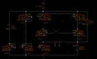
thanks for the help. However, above circuit needs a square waveform for triangular waveform generation. I found another circuit in [1] shown in figure below. Theoretically circuit should work as follows:

M7,M5, M4, M3 and M2 form current sources while M1 and M0 act as complementary switching transistors. When power supply is turned on, Either M1 or M0 will turn on earlier than other. Let us suppose M1 turns on earlier than M0. This charges C0 through M3 and R1, causing M1 drain voltage to rise up. M1 drain voltage is connected with M0 gate. After a certain limit. M0 gate voltage will go above Vth and turn on M0 causing C0 to discharge through M2 and M6. This will increase M0 drain and M1 gate voltage and after sometime M1 will turn on. In this way two transistors M1 and M0 will turn-on and turn-off alternatively causing a triangular waveform to appear at their sources.

I am having problem in order to start the simulations in cadence. In real life either M1 or M0 will turn on earlier than other. How can i do this in simulations?. How should i start the simulations.

regards


[1] P. V. ANANDA MOHAN, "A new triangular waveform generator", IEEE Trans on instrumentation and measurement, 1978.
 

Attachments

  • trigen.png
    trigen.png
    40 KB · Views: 112

Hi,

For right simulation generating circuits you must set start condition or place kick start source (vpwl or ipwl), where you set kick voltage/current peak in first moment.
 
Hi Sarge,

Can you tell where should i put these sources(vpwl or ipwl) in circuit?
 

Ipwl - between drains of M0 and M1.

Vpwl - for example, in series with drain M1 and drain M3.
 
And small advice :)
Don't connect body terminal on gnd/vdd net if you don't need changing of Vth.
 
Hi Sarge,

I am sorry for very basic question but i have never used ipwl and vpwl sources. Can you tell what settings should be put in them
 

No problem
This is properties of ipwl, which i use to simulate LC VCO:
IPWL_prop.png
 
Another way to do this is by setting a starting condition. You can do this at ADE menu under convergence aids or something.
 
How triangular does it have to be? Perfect, or just
"sort of ramp-y"?

I've made ramp generators with switched RC, and
ramps with switched or steered current source onto
a capacitor. Both use limit comparators for the
endpoints, banging a SRFF.

The scheme gets flakier when your period approaches
the order of comparator+FF delay, you'll see the
emdpoint (peak, valley) voltages move w/ temp and
so on (depending on the quality of your comparator
design, mostly).
 

Hi Sarge,

Did your made circuit work. Atleast i copied the whole circuit you made and it is not working properly?


Hi,

What about simple charge-pump circuit?

I tried to make simple circuit:
View attachment 101417
Output waveform:
View attachment 101418

Looks like it may working :)
You only need precise current source.

- - - Updated - - -

Hi dick_freebird

I need a precise triangular waveform generator which can switch from 0 to 1.2V with 1.2V power supply.


How triangular does it have to be? Perfect, or just
"sort of ramp-y"?

I've made ramp generators with switched RC, and
ramps with switched or steered current source onto
a capacitor. Both use limit comparators for the
endpoints, banging a SRFF.

The scheme gets flakier when your period approaches
the order of comparator+FF delay, you'll see the
emdpoint (peak, valley) voltages move w/ temp and
so on (depending on the quality of your comparator
design, mostly).
 

Hi Sarge,

Did your made circuit work. Atleast i copied the whole circuit you made and it is not working properly?

Yes, it works for me.
Can you show your circuit with input/output waveforms.
Don't forget that you must carefully choose capacitor value (du/dt = i/C).
 
I need a precise triangular waveform generator which can switch from 0 to 1.2V with 1.2V power supply.

You have some problems in this case.

One is, you're not going to get a current source which has good fidelity
rail-to-rail without taking some elaborate measures, and even so you're
liable to not keep the current constant as you approach either rail. There
is always headroom needed.

Two, desiring to switch exactly at the rail means you're trying to track
a fine voltage error in an asymptotic region and your time-jitter will probably
be pretty bad.

An approach might be to (say) make a ramp w/ switched current-source
and capacitor, but put the switchpoints at VDD/4 and 3*VDD/4 (for a
VDD/2 voltage swing) and then post-amplify it at A=2, VCM=VDD/2. You
still have the issues of how close to the rails you can get without
"unacceptable" loss of fidelity, but you can probably find a "good enough"
rail-rail op amp somewhere.

But those op amps are likely to be slow and hopefully you do not need
this triangle wave to be especially fast. Otherwise slew rate distortion
may add to your problems.
 
Thank you for help....I modified circuit present in [1] to meet my requirements. Now the circuit is better suited for integrated circuit applications. Only capacitor need to be off-chip. Even though the circuit is not operating as 100% rail to rail but still it is good enough to meet my requirements.

- - - Updated - - -

[1] P. V. ANANDA MOHAN, "A new triangular waveform generator", IEEE Trans on instrumentation and measurement, 1978.
 

Status
Not open for further replies.

Part and Inventory Search

Welcome to EDABoard.com

Sponsor

Back
Top