Continue to Site

Welcome to EDAboard.com

Welcome to our site! EDAboard.com is an international Electronics Discussion Forum focused on EDA software, circuits, schematics, books, theory, papers, asic, pld, 8051, DSP, Network, RF, Analog Design, PCB, Service Manuals... and a whole lot more! To participate you need to register. Registration is free. Click here to register now.

Transmitter for Digital signal

Status
Not open for further replies.

naspek

Member level 1
Member level 1
Joined
Feb 17, 2010
Messages
37
Helped
0
Reputation
0
Reaction score
0
Trophy points
1,286
Activity points
1,546
Hey there.. got question here..
i been searching around the net.. but still didn't get any answer for my question..

An analogue source produces an audio and video signals. Explain with a transmitter block diagram, how the two signals can be transmitted with other digital signals over a noisy bandpass channel.

Please.. give me an idea to answer this question.. thanks! =) :-|
 

Digital Modulation of those analogue signals would help transmit them, by introducing Phase shift keying or Amplitude shift keying.
 

I'm assuming you are asking how so many channels coexist in the same wire or fiber.

The digital signals do not go in as square waves or pulses. They would mix together and become indistinguishable.

Instead each channel occupies a narrow range of the frequency spectrum. Its assigned band.

The digital signal is coded so a low becomes a sine wave of one frequency, while a high becomes a sine wave of another frequency. Either that, or it alternates between less and greater amplitude of one sine wave frequency.

I would imagine analog transmissions can coexist with the above method. Because analog transmissions are already in the form of sine waves (amplitude modulation or frequency modulation).

What goes through the wire or fiber? A mix of sinewaves.

Each channel is extracted using a narrow-band-pass filter.

If you're asking how electrons can vibrate back and forth in the wire so fast as to match the instantaneous sum of 1000 different sine waves...

Or asking how photons traveling through a fiber on so many wavelengths... can arrive at the other end and make their individual mark on the detector so as to be filterable...

That part does defy understanding. I wouldn't think it could work, except we find it does work.
 
Hi BradtheRad,

The digital signal is coded so a low becomes a sine wave of one frequency, while a high becomes a sine wave of another frequency. Either that, or it alternates between less and greater amplitude of one sine wave frequency.

Are you referring to frequency modulation here?

I am also confused with transmission of bits through radio channels, after the bits are converted to symbols, how are the symbols transmitted in the air as analog signal? Or if my understanding there is wrong please correct me.

Thank you
 

I thinking you are mixing up 2 things.

> Digital data always remain digital i.e represented in 1s and 0s. But they can never be transmitted as 1s and 0s through any kind of channel(by channel i mean any interface such as Air e.g in microwave or antenna communication , guided interfaces such as waveguides or fiber-optic cables etc). For such data transmission we perform Digital modulation such as QAM, BPSK,QPSK, FSK, ASK etc etc. After which they are demodulated back to 1s and 0s.

>Secondly, if you are not transmitting data through any interface rather moving that data from one chip to another chip on a single board or inside a single chip then digital data can have multiple types of representation (which we also call baseband signals because of the presence of finite DC value in the signal) such as Pulse width modulated, Pulse phase modulation, NRZ, RZ and such types of signals which are also digital but can travel on the data lines. Remember a signal is always Analog during transmission ,it is the initial data transmitted from a transmitter and the final data received at the receiver on which we decide that it is a Digital Data transmission or an Analog Data transmission.
 

For such data transmission we perform Digital modulation such as QAM, BPSK,QPSK, FSK, ASK etc etc. After which they are demodulated back to 1s and 0s.

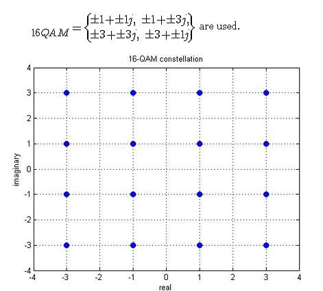
I understand that it is analog signal that is sent between antennas ( for wireless communications) but sometimes the bits (after modulation, take M_QAM for example) are represented by complex number (mapping of constellation)

68_1317273859.jpg

Scaling factor in QAM

and there is MATLAB function that produce this symbols for a specified value of M, like given:

hmod = modem.qammod(16);
tx = randint(500,1,16); % producing random numbers to be transmitted
qamSig = modulate(hmod,tx);

what are these numbers really and how are they related to the analog signal produced by modulation???
Thank you
 

what are these numbers really and how are they related to the analog signal produced by modulation???
Thank you
These values represent the amplitude and phase of a modulated signal. If it is digitally modulated then we have 16 digital possibilities in this case of 16QAM
0000 = A cos(wt + theta1)
0001 = B cos(wt+theta2)
0010 = C cos (wt+theta3)
0011 = D cos(wt+theta4)
and so on ......

the R.H.S values are transmitted by the modulator and then are decoded(demodulated) at the other end to get the digital signal back.

for e.g in BPSK Binary Phase shift keying (the most simple and understood0
has two digital states '0' and '1'

0 = A cos(wt+90)
1= B cost(wt+180)

that is two distinct states on the polar axis.
 
Last edited:

i understand that part of modulation, what i meant was the complex number representation of each symbol...

as for the MATLAB simulation, hmod = modem.qammod(16);
tx = randint(500,1,16); % producing random numbers to be transmitted
qamSig = modulate(hmod,tx);

the result of modulation, qamSig is a vector of complex numbers... That is where i stumbled...

thanks
 

Are you referring to frequency modulation here?

I am also confused with transmission of bits through radio channels, after the bits are converted to symbols, how are the symbols transmitted in the air as analog signal? Or if my understanding there is wrong please correct me.

Sorry I forgot it helps to give an example.

A low might be coded by sending ten microseconds of 1 Mhz sine wave.

A high might be sent as ten microseconds of 1.5 Mhz sine wave.

Call it a cousin of frequency modulation.

It's similar to how computers wrote data to cassette tape. Or how telephone modem communication is done.

Or on the other hand, an example of using amplitude:

A low might be transmitted as a 1MHz sinewave for ten milliseconds at 1V amplitude.

A high is the same but at 2V amplitude.

I think AM is used less since it's liable to misreads due to occasional glitches.

The above is only an example of the simplest kind of binary transmission.
 

i understand that part of modulation, what i meant was the complex number representation of each symbol...

as for the MATLAB simulation, hmod = modem.qammod(16);
tx = randint(500,1,16); % producing random numbers to be transmitted
qamSig = modulate(hmod,tx);

the result of modulation, qamSig is a vector of complex numbers... That is where i stumbled...

thanks

oh that yes well those complex numbers are a way to plot the signal on the Real Imaginary axis. Actually it is the amplitude and phase that is being changed or modified
 

I am lost here, how does a complex number = signal?
Thanks

if we have a complex number a+jb , then R= √a^2+b^2 is the magnitude and Φ = INVtangent (b/a) right.

so these values are the magnitude and the phase of the signal transmitted as
e.g
R cos (wt+Φ)
and so on
 
I see! THANK YOU!!! So that's how the complex number represents the Amplitude and phase of each of M signals?
And that signal is the result after M-QAM right?
 

I see! THANK YOU!!! So that's how the complex number represents the Amplitude and phase of each of M signals?
And that signal is the result after M-QAM right?

I would suggest you to read Digital Communication Books such as Digital Communications: Fundamentals and Applications (2nd Edition) by
Bernard Sklar (Author) for more understanding and clarity . Try to understand things beyond simple baseband representation of signals and look into the real signals. Use ADS which has a wonderful array of communication systems (in examples) and you can design urself as well , as actually what is happening when we transmit using QAM or QPSK etc.
 

Use ADS which has a wonderful array of communication systems (in examples) and you can design urself as well , as actually what is happening when we transmit using QAM or QPSK etc.

Thanks but what is ADS?
 

Status
Not open for further replies.

Similar threads

Part and Inventory Search

Welcome to EDABoard.com

Sponsor

Back
Top