Mark Baseggio
Junior Member level 2

Hey folks,
I'm designing an IR remote that can be controlled over the Internet using a Raspberry Pi and LIRC.
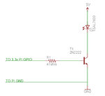
Since the Pi GPIO is 3.3v, and you're only supposed to source a max of around 18mA from each pin (or 50mA @ 3.3v total from all pins) I need to use something to give the TSAL7600 IR LED more power. Here is my circuit (note R1 is 220 ohms now not 47):

This design is "borrowed" from the TV-B-Gone (see the IR-Driver Transistors section), but the voltages are different. I want to make sure that I'm doing this right, so I don't blow up the Pi and also so I get the most power possible out of the IR LED. I'd like to turn this into a shield for the Pi at some point when I perfect the design.
I also put the design into Falstad's Java applet circuit simulator and realized I would have waaay to much current so I changed R1 to 220 ohms. See here: Simulated circuit
But I'm not satisfied that this takes everything into account and want to really learn more about what I need to consider when using transistors like this.
The LED is pretty beefy, datasheet for the TSAL7600 is here: https://www.mouser.com/catalog/specsheets/tsal7600.pdf
I'd appreciate your feedback! Thanks very much for your time.
I'm designing an IR remote that can be controlled over the Internet using a Raspberry Pi and LIRC.
Since the Pi GPIO is 3.3v, and you're only supposed to source a max of around 18mA from each pin (or 50mA @ 3.3v total from all pins) I need to use something to give the TSAL7600 IR LED more power. Here is my circuit (note R1 is 220 ohms now not 47):

This design is "borrowed" from the TV-B-Gone (see the IR-Driver Transistors section), but the voltages are different. I want to make sure that I'm doing this right, so I don't blow up the Pi and also so I get the most power possible out of the IR LED. I'd like to turn this into a shield for the Pi at some point when I perfect the design.
I also put the design into Falstad's Java applet circuit simulator and realized I would have waaay to much current so I changed R1 to 220 ohms. See here: Simulated circuit
But I'm not satisfied that this takes everything into account and want to really learn more about what I need to consider when using transistors like this.
The LED is pretty beefy, datasheet for the TSAL7600 is here: https://www.mouser.com/catalog/specsheets/tsal7600.pdf
I'd appreciate your feedback! Thanks very much for your time.
