Continue to Site

Welcome to EDAboard.com

Welcome to our site! EDAboard.com is an international Electronics Discussion Forum focused on EDA software, circuits, schematics, books, theory, papers, asic, pld, 8051, DSP, Network, RF, Analog Design, PCB, Service Manuals... and a whole lot more! To participate you need to register. Registration is free. Click here to register now.

[SOLVED] Transistor input to microcontroller: what uses less current

Status
Not open for further replies.

gmorfeus

Junior Member level 1
Joined
Nov 19, 2012
Messages
19
Helped
0
Reputation
0
Reaction score
0
Trophy points
1,281
Location
Croatia
Activity points
1,497
Hi,

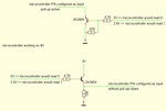
I am designing a circuit that has GPRS communication. The modem has an STATUS output but datasheet mentions only how to put a LED as in indicator (standard connection when LED is in collector side with an 300ohm resistor and emitter is connected to GND). I asked manufacturer if I can connect STATUS pin to the microcontroller PIN configured as input but they said better not to and that there is an AT command to figure out if modem is ON or OFF. Well, I would be happier to know it also "electrically":) What I am not sure is if it is better to use NPN or PNP transistor for the task? As most of the time the modem will be ON, I would like to use as less current as possible to sense the modem ON/OFF state. By your opinion, what's better to use between designs attached in the post? Thanks!
microcontroller.jpg
 

Hi, if I've understood your description and the schematic correctly, and with the little I know, I'd go with the NPN set-up. However, as you say the modem will be mostly on, that's perhaps the most wasteful option, as one would think the PNP would use less power, because it'll be "off" whenever the modem's on.
I have a doubt about that PNP set-up, as in my naivety I'd have thought the microcontroller were intended to supply the positive voltage to the transistor, which I don't understand how it does that if it's configured as an input, but that's my lack of experience with microcontrollers.
I hope a better-informed person answers this for you as my theory may be wrong.


It's an open collector input pin on the microcontroller (isn't it?). Memory's failing me it seems. I think the PNP is the better choice.
 
Last edited:

Check the input high threshold of the micro, the NPN circuit will lose Vbe between input voltage and the output so it may not reach logic 1 anyway.
With the top circuit, you might be able to replace it all with a Schottky diode, cathode to the signal source side.
For the bottom circuit, consider removing the transistor and 10K resistor the connecting a Schottky diode between the micro side and 4V.

Although both methods fail to make 0V and 4V logic levels exactly, they would draw no active current at all.

Brian.
 

The first one (pnp based) cannot works because the base voltage cannot reach (roughly) 4-0.6 = 3.4V to switch the transistor off.

In the second one (npn based) the emitter voltage will be roughly 0.6 V less than the base voltage so it will be 2.2 V. Is it enough for you ?

However, in general is better to provide an open collector output to the micro, using a pullup connected to its own supply. If you need non-inverting operation two cascaded npn transistor are required.
 
Hi,

thanks for all your opinions and possible solutions. As I understand all together, the best would be to use open collector and then in the microcontroller SW "invert" the logic: logical 0 would mean GSM on, and logical 1 would mean GSM off.
Schematic:


Will 4.7k be "small enough" to have transistor in saturation or I shall lower resistance down to 1k?
 

If the source can sink current you can dispense with the 47K resistor. The calculation is Ib = (pull-up current/transistor Hfe) then to ensure saturation multiply it by 10.

The pull-up current in most microcontrollers is only a few uA but for safety, lets assume it is much higher (the data sheet will tell you the actual figure) at 100uA. If you use a transistor with a Hfe of 100, the base current will be (0.0001/100) Amps or 1uA. From a 2.8V source, the bias resistor would drop (2.8-Vbe) or about 2.2V and the base resistor would be (2.2/1uA) = 2.2M so allowing ten times the current for saturation you could safely use 220K. Using 4.7K won't do any harm but there is certainly no reason to make it smaller.

Brian.

Hi Brian,

what exactly do you mean by this sentence: "If the source can sink current you can dispense with the 47K resistor." I can leave 47K out if the source can sink current? Hm, I think it won't be a good idea, while "STATUS" pin on GSM is marked as output and on the lower voltage level than microcontroller...
All together, my last schematic would be just OK and I can only make bigger resistor for Rb (but also 4k7 is fine)?

Gabrijel
 

What I mean is something has to bring the base voltage to near zero for the transistor to stop conducting. If the GSM output goes to zero, it will remove the bias without needing the resistor at all. You only need the 47K resistor if the voltage source disconnects and leaves the series resistor floating.

4K7 if fine but if you want to reduce the current consumption slightly, you can make the value bigger. You only need about 10uA base current but the 4.7K will pass (2.8-0.6)/4700 = 468uA. No harm will be done, it is still a small current and well within the transistors rating but the extra is wasted.
Brian.

Hi Brian,

thanks for you explanation It was a real help and I also learned something new. I will put 100k for the base resistor (as transistor will be mostly on) just to save some small current.

Kind regards,
Gabrijel Erman
 

Status
Not open for further replies.

Part and Inventory Search

Welcome to EDABoard.com

Sponsor

Back
Top