Continue to Site

Welcome to EDAboard.com

Welcome to our site! EDAboard.com is an international Electronics Discussion Forum focused on EDA software, circuits, schematics, books, theory, papers, asic, pld, 8051, DSP, Network, RF, Analog Design, PCB, Service Manuals... and a whole lot more! To participate you need to register. Registration is free. Click here to register now.

Transistor Ignition Schematic needed

Status
Not open for further replies.

easy.rahil

Newbie level 3
Newbie level 3
Joined
Jul 17, 2011
Messages
4
Helped
0
Reputation
0
Reaction score
0
Trophy points
1,281
Activity points
1,316
Hello All experts, I have read almost all articles regarding ignition in here. most of thm have no answer and others has answer with no solutions.
I m trying again with all electronics guys. I want to replace my point breaker system with transistor ignition which will be easy and reliable for me. i have two stroke RD350 double cylinder motorcycle. i found many ckts on net but most of thm are copy of someone else design only and do not give reply back to any questions.
i found one and think its easiest in all of thm available on net.
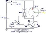
image attached:
277pic2.jpg

it is with hall effect system.
if anybody can help making this or pulse coil type transistor Ignition, will be appreciated .
thanks in advance
 

Dear Kak,
thanks for your reply, i read all articles and these are CDi which needs most of the components replacement, like magneto change, HT coil change because CDi based of AC current a nd TCi works with DC current. as my bike running with DC and simple TCi need very few components as shown in picture. i have found one article useful "Electronic Ignition DIY Google Docs" but it has no Pulse Input and it uses Point breaker for triggering. if anybody can modify it for pulse trigger input it may work well.
Thanks
 

i have checked the link you given but its very complicated thing which i think i cannot make and will face component shortages in local market. i will prefer this ignition_coil_driver_circuit_diagram_2.jpg
and here is the parts list:
TR1 StandardIgnition Coilor Induction coil
T1 BFY51 Small Transistor
T2 2n3055 Power Transistors or HV MOSFET or IGBT( use modern component "IRGB4061DPBF")
R1 100 Ohm Resistor
D1
1N4007 will do but preferably a Schottky Diode

RC1 0.1µF Capacitor + 10K Resistor (R1 should be 1 watt or more.
RC1 should be 10W, and 1kV. You can use a variety of values here. I often use a 1kV 220nF capacitor with a 50W 120R resistor. You may have to determine experimentally what values work best at the frequencies and duties you will use.)

YOU ALL CAN SEE THESE IN THREAD here(

Can anyone edit this schematic as i think is not correct or just let me know if it is perfect to make. RC1 is confusing me ! wht values.?
Heard about ATOM IGNITION system also. anybody knows?
 
Last edited:

i m really surprised that nobody belongs to such schematic or automobile ignition.
 

Status
Not open for further replies.

Similar threads

Part and Inventory Search

Welcome to EDABoard.com

Sponsor

Back
Top